Continue to Site

Eng-Tips is the largest engineering community on the Internet

Intelligent Work Forums for Engineering Professionals

  • Congratulations IDS on being selected by the Eng-Tips community for having the most helpful posts in the forums last week. Way to Go!

Tracking the displacement of a centerpoint pipe. 2

Status
Not open for further replies.

Le_Mickster

Mechanical
Dec 5, 2019
10
Hi all, I am currently looking into the matter of applying some loads to a large structure consisting of many components.
To make it all simpler I have added a picture to resemble my problem.

I'd like to somehow track the displacement of the pipe center as shown:
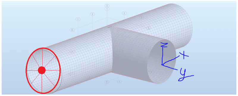
Coupling_cybzum.png


It'd be awesome, if I somehow could track this. I don't know if it has to be an average of nodes on the circle.

I have thought about a kinematic coupling could be the solution, but I'm not really interested in imposing any boundary conditions other than tracking what happens at the center of the pipe.

Best regards

Mick
 
Replies continue below

Recommended for you

Interesting question. I have two ideas:
1. Create a reference node in the center and connect at least 4 points on the pipe edge with that ref node through soft spring. I would think that the ref node then stays approximately in the center. With output variable COORD you could also get field output for the current coordinates of nodes.

2. Create a set for each pipe edge you are interested in. Request COORD as field output. Run the analysis. Use a Python script to calculate the average x,y,z for each set of nodes. I think I already have a script working on a another variable and could modify it to work with COORD1,2,3.
 
It depends on how the pipe is loaded. If there’s no internal pressure and this edge is not loaded too then you could use MPC type LINK to measure the deflection of the reference point in the middle. In other cases this would apply undesirable constraints to the edge.

Safest way is to place user CSYS there and extract undeformed and deformed coordinates of nodes on the edge. Then you can calculate the displacement of the center of the circle formed by these nodes (of course this can be automated using scripts or external software such as SciLab).
 
Hi again and thanks for listening. I am currently looking into coupling kinematic/distributing. But I guess I have to use a script somehow as both of you have suggested. Maybe if I get time I'll try and compare the coord results to the results gained using the soft spring.

The component I am working on is a wide pressure tank which is subject to both thermal and pressure loading.

Mustaine3, do you have an example of the Python-script I can see perhaps?
 
I've modified my script and attached it.
But I've recognized, that the average isn't really working. When you have more nodes on one side of the egde, then the average is misleading. I've used now the average of the min und max position value. It's also not perfect, but a bit better.

In the script the operation is done on all sets with the name xedge inside. Adopt it to your set names.
Be aware that the output is based on the currently displayed result frame.
 
 https://files.engineering.com/getfile.aspx?folder=8de62720-c147-4fc3-9a94-cb42563e5839&file=Script_avrg_position.py
One more idea is to cap the end of the pipe with thin low stiffness shell and request the displacement of its middle node. You can use tie constraint to connect it to the actual model.
 
Hi mgriebel - is this possible? I think I want the reversed result - instead of imposing a load/moment/displacement I want to register the displacement of a reference node.
 
That’s right, distributing coupling is yet another way to do this. I just ran a simple test to make sure it works as expected and I can confirm that this method is safe to use.
 
A distributing coupling is an interpolation element - it interpolates the average motion of the cloud nodes to the reference node. It is equivalent to an RBE3 if you are familiar with Nastran.
 
mgriebel - thank you. I am not familiar with Nastran, but I will look into the manual and read about the RBE3 element. As I wrote in my second post I was actually looking into the coupling of kinematic and distributing, but I understood it solely as imposing kinematic constraints and loads/moments.
I'll try it out during the day and give an update.
 
Ok, I can't seem to get Abaqus to even solve this.

image_jrasah.png


What I have done is:

image_dyooky.png


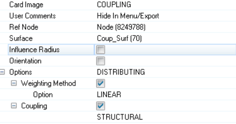
With the following card:

image_jbbfmk.png


I have tried both with and without the coupling and weighted option enabled.

I am using HyperWorks - do you have any suggestions?
 
I thought you are using regular Abaqus/CAE environment. But the keywords should be the same. Can you show part of the generated inp file with coupling definition ? Did you try with Uniform weighting method ?
 
Hi again FEA way. I am using the Abaqus solver, so everything should be the same. HyperMesh is just an excellent tool for pre-processing and mesh-control. I am using the Abaqus user-profile so it should be the same in the input file.

The inp file:
image_ahcnww.png


I just created a node in the middle - it's just a reference node. I have not added the DCOUP3D elements anywhere - maybe this is part of the problem?
My surface is consisting of the following:
image_cwazvy.png


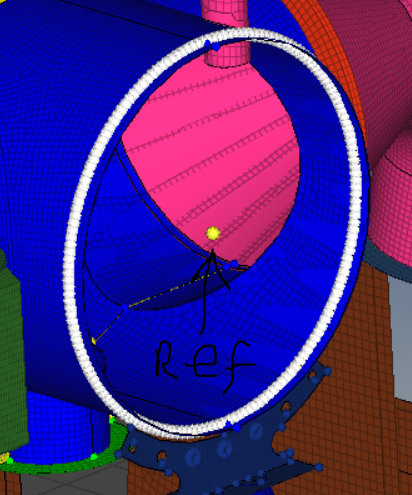
Where: N_Set_Manifold is consisting of nodes on the circle shown in my previous post - the nodes are associated with S4 elements.

Best regards
Mick
 
It’s only necessary to define coupling elements when you use the *DISTRIBUTING COUPLING keyword (but this method is not recommended). Change your surface definition to:

*SURFACE, NAME=Coup_Surf, TYPE=NODE
N_Set_Manifold, 1

The last item in the first data line is distributing weight factor.
 
I thank you, dear Sir.

With regard to the coupling method - I'd guess that when I use shells, that structural is the way to go, as the shells I use have rotational D.O.F's.

With regard to the two coupling methods (structural and continuum) - it seems that continuum is default. I use shells and have therefore rotational D.O.F's, so I guess I should use the structural coupling method? Or is this addition of coupling method necessary? :)
 
Indeed the default type of distributing coupling is continuum. And it’s also true that for shells it’s better to use structural type.
 
If you're using Hypermesh, the easiest way to create a distributing coupling element is:

1D > rbe3

dependent > calculate node (will determine the approximate area centroid)
independent > select your nodes
dependent dofs > keep all selected (unless you don't want one of the DOF coupled)
weight > 1 is good for what you're doing
elem types > coup_dis

I would not use structural coupling unless you have a very specific need for it (usually colinear nodes on the end of a shell where you want to transfer the bending moment). Using the rotational DOF of the independent nodes can cause issues. Continuum is the way to go. It will still calculate average rotations at the dependent node, it will just be based on the average "swirl" of the independent nodes.
 
mgriebel

I got the solver to converge with the surface consisting of nodes and the yellow reference node in the middle.

Would you suggest using the distributing coupling element with 1D -> RBE3 method instead, and if so - why?

Or are both methods for tracking and obtaining the centroid coordinates similar?
 
No, that menu just automates the creation of the distributed coupling element. Creating it through the model tree is also acceptable, just takes a bit more input. The only suggestion I would give is to avoid structural coupling.
 
Status
Not open for further replies.

Part and Inventory Search

Sponsor