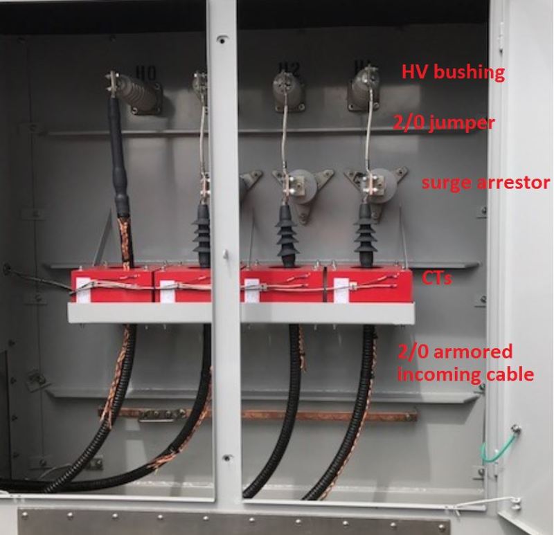
Best practice would be to avoid marshalling the main connections on the arrester, or using an arrester for conductor support. In that way a failed arrester can be easily disconnected and the main plant returned to service.
Ideally the main current carrying conductors would connect straight to the bushing, but in the photograph the installer has made the best of the physical arrangement.
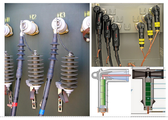
That is how we were taught too although I had a different opnion especially with most of our pole mounted distribution trafos had the surge arrestor mounts below the main bushings. Droppers go to the arrestors first then only to the bushings.
On querying this with one of our company engineers the explanation was that as a surge or spike travels along the conductive path you want it to reach the arrestor before entering the transformer. See the pic despite the 2 blown arrestors... just to show the mounts in relation to the bushings.
I agree with Marmite. Arrester failures cause outages, and should be installed so they can be easily disconnected if possible. Also note that three current carrying pad to pad connections are used where one would do, tripling the chance of a connection failure.
I originally counted 1 at the bushing and 2 at the arrester. At the arrester the load current travels from the termination pad, to the arrester pad sandwiched in between, and on to the cable pad. On second look, I believe the arrester pad is on the outside, and the there is only 1 load current carrying connection at this point. It still means two connections where one would do.