Continue to Site

Eng-Tips is the largest engineering community on the Internet

Intelligent Work Forums for Engineering Professionals

  • Congratulations KootK on being selected by the Eng-Tips community for having the most helpful posts in the forums last week. Way to Go!

Transformer diff protection connection

Status
Not open for further replies.

comuniti

Electrical
Jun 19, 2019
2
Hi all,
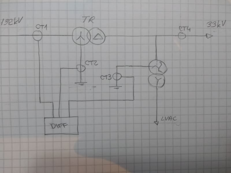
I found some old drawings which include TR diff protection (please see attached picture). CT1, CT2, CT3 are connected to Differential relay and CT4 is used for meters (each CT has more cores, but to be easier I shown only that for diff prot.).
This connection is a little bit confusing for me...
Is this a correct connection for diff prot.? Is this going to work properly?
Why CT4 is not included in diff prot.?

Thank for your help.
 
 https://files.engineering.com/getfile.aspx?folder=fe3ba16b-ef7f-4e7d-8648-2ad8e03d79b2&file=Diff_prot.jpg
Replies continue below

Recommended for you

CT1 and CT2 can form a REF zone. I don't see how CT3 helps as is. I'd bring in CT4 and add CT5 below the zigzag-wye transformer; then you'd have enough for a differential.
 
comuniti,
I too think that the scheme doesnot work properly.
1) CT1 & CT2 looks connected properly. It will work as REF (87N/ PNDF) for the high side. But the issue is since the
WYE side of TR is solidly grounded do you need a REF scheme? Because the high ground fault currents on 132kV side
might cause saturation issues and give nuisance tripping for out of zone ground faults, if the REF element of the
relay is low impedance type.
2) Connecting CT3 to the relay does not make any sense to me. Because a GF on the 33kV side has no impact on to the 132kV
side GF protection.
3) CT3 (NCT) & CT4 (Phase CTs) should have been connected to another Diff relay to achieve REF (87N) protection for the 33kV side.
Because 33kV side is DELTA connected.
4) CT1 (Phase CTs) & CT4 (Phase CTs) SHOULD have been connected to the existing relay to achieve Diff (87T) protection.

Do you like to share the relay make & model?


Transformer differential protection is between CT1 & CT4.
The neutral CT2 & CT3 are required (together with the corresponding phase CTs) for Low impedance REF protection of HV and LV windings respectively.
Excluding or not showing CT4 connection to the relay doesn't make sense.
 
I have the same view with RRaghunath!
With this scheme you have only low. imp. REF protection. To achieve diff. TR you definitely need CT4 to complete the scheme.
 
Just re-attaching original as inline image.

Diff_prot_jerhmf.jpg
 
CT1 and CT4 are enough for differential protection if zero sequence currents are filtered out (CT4 should be included).

Excerpt from Siemens 7UT6 relay (similar in 7UT8): "The disadvantage of elimination of the zero sequence current is that the protection becomes less sensitive (factor 2/3 because the zero sequence current amounts to 1/3 in case of an earth fault in the protected area".

CT2 and CT3 can be used in differential protection to perform the so called "Io-correction" (to avoid the aforementioned decrease in sensitivity). See an example for wye side from Siemens 7UT8 relay manual (attached as an image).

CT2 with CT1 and CT3 with CT4 can be used for REF as well, if required.

 
Status
Not open for further replies.

Part and Inventory Search

Sponsor