Navigation
Install the app
How to install the app on iOS
Follow along with the video below to see how to install our site as a web app on your home screen.
Note: This feature may not be available in some browsers.
More options
Style variation
-
Congratulations TugboatEng on being selected by the Eng-Tips community for having the most helpful posts in the forums last week. Way to Go!
You are using an out of date browser. It may not display this or other websites correctly.
You should upgrade or use an alternative browser.
You should upgrade or use an alternative browser.
Transformer Inrush Value
- Thread starter wbd
- Start date
- Status
- Not open for further replies.
Skogsgurra
Electrical
What size is the transformer? Small ones usually have fewer cycles with inrush. Really small ones don't have more than half a cycle while large ones can have up to 20. It also depends on grid impedance, low impedance makes inrush higher and also for more periods. The xfrmr manufacturer should be able to guide you.
Gunnar Englund
--------------------------------------
Half full - Half empty? I don't mind. It's what in it that counts.
Gunnar Englund
--------------------------------------
Half full - Half empty? I don't mind. It's what in it that counts.
Inrush is a complicated event. The size and type of the transformer also has an impact. For oil-filled transformers, I used 10X for 0.1 sec and don't have any problems. Most relaying guides suggest 8X as a rule of thumb. For large dry-type transformers, it needs to be higher. 13X to 15X as I've learned the hard way.
HamburgerHelper
Electrical
It is more the larger the transformer on a per unit basis. You should see if you can put harmonic blocking on so that you don't have to set the curves so loose.
------------------------------------------------------------------------------------------
If you can't explain it to a six year old, you don't understand it yourself.
------------------------------------------------------------------------------------------
If you can't explain it to a six year old, you don't understand it yourself.
RRaghunath
Electrical
The IEC on fuses (IEC 60282 & 60787) suggests
* 12x current for 100ms and
* 25x current for 10ms
as recommended pre-arcing time, for selecting the HV fuses for transformers.
* 12x current for 100ms and
* 25x current for 10ms
as recommended pre-arcing time, for selecting the HV fuses for transformers.
We wonder if there is a more accurate method to determine the appropriate inrush current on power transformer rather than use a deterministic value to address a random inrush current phenomenon.
Inrush current is known from around 100 years. Some background in this topic is listed below
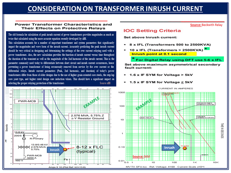
a) Popular setting Current: RMS Value 8-12 x FLC @0.1 s (from energization t=0 to the selected time)
b) Instantaneous Peak value: 8-30 x FLC. The probability to reach Inrush current >20 x FLC is relatively low.
c) Empirical Approach: Based in electromechanical relay based on a 1944 AIEE (former IEEE).
d) Steel Core Material: Modern transformer is built with available better technology and materials with lower inrush current
e) Transformer Protection: Modern Microprocessor base relay, has better capability to restrain on inrush event tripping while being capable of tripping when energizing a faulted transformer with Properly restraining
See below additional info from multiple sources

No question that there are more accurate methods to predict inrush. But the "inrush point" rule of thumb has the advantage of being easy to apply. It's also relatively simple in many cases to block the instantaneous trip when energizing the unit. But in most cases, the instantaneous trip on the primary relay also needs to be set above the maximum through-fault current, and that is normally higher than the inrush. Fuses are a different story, of course.
Skogsgurra
Electrical
I made these recordings for an article (in Swedish, sorry) about inrush on a smaller scale. It is taken on an 850 VA transformer and a 230 V supply. Not exactly high-power, but the wave-forms are strikingly similar.
[URL unfurl="true"]https://res.cloudinary.com/engineering-com/raw/upload/v1550019794/tips/Transformer_inrush_summary_for_EngTips_1_kbqzhr.docx[/url]
Gunnar Englund
--------------------------------------
Half full - Half empty? I don't mind. It's what in it that counts.
[URL unfurl="true"]https://res.cloudinary.com/engineering-com/raw/upload/v1550019794/tips/Transformer_inrush_summary_for_EngTips_1_kbqzhr.docx[/url]
Gunnar Englund
--------------------------------------
Half full - Half empty? I don't mind. It's what in it that counts.
Hi dpc,
It is understood that for small power transformer the rule of thumb (X time FLC) works satisfactorily for most practical applications.
However, we are curious to see how other users of medium size and large power transformer avoid false tripping by inrush current. It is also known that a conservative approach such as 12 x FLC @ 0.1 seconds or so do not provide the optimal setting. Any thoughts?
I prefer to use a curve rather than a point, otherwise you might be tempted to wrap your protection curves around that point. Looks to me like cuky2000 might be getting close to pickup on the right hand curve if extended to 25X at 0.01, and on the left if extended to 6X at 1.
If this is a large unit with differential protection, making the instantaneous trip highly sensitive is not really necessary. I would err on the conservative side. It's actually more problematic for transformers protected only with primary fuses, since the fuse TCC is more or less fixed, and replacement in the event of a nuisance trip is more difficult than resetting a relay. It can also be an issue for smaller tranformers protected with molded case circuit breakers. For larger transformers the instantaneous trip (primary) needs to be set above the maximum secondary fault current, and in many cases this will be higher than the inrush current unless the impedance is very high.
Gunnar - were the transformers unloaded on the secondary when energized? Just curious. Thanks for posting.
Gunnar - were the transformers unloaded on the secondary when energized? Just curious. Thanks for posting.
Skogsgurra
Electrical
@ dpc
Not loaded. The problem that was discussed is common in automation systems where the whole system is fed via an isolation transformer. The transformer provides energy to the different units, which are connected as needed. Switch-off is in reverse order with transformer being the last unit to be disconnected. High-powered units like motors are fed directly from the 400 V system and do not affect transformer.
The demagnetizing will not work well if the secondary is loaded - Q gets too low. Not much ringing. But I guess that even that could help instead of dissipating magnetic energy as a breaker arc and (some) HF radiation. That locks the remanent flux on random levels and adds to the problem.
Gunnar Englund
--------------------------------------
Half full - Half empty? I don't mind. It's what in it that counts.
Transformer manufacturers can furnish the inrush peak value with reasonable accuracy. Frankly this is not much affected by the quality of silicon steel. Mainly depends on inductance of winding( depends on inner diameter, number of turns )working flux density and remanent flux. When we say 10 times full load current, is it inrush peak/peak of full load or inrush/RMS full load current?
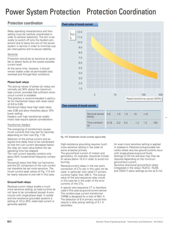
Below is a graph showing the estimated Inrush range vs. transformer MVA rating. The graph indicates that the Inrush current decrease as the transformer MVA increases. The inrush current values in the graph are lower than the numbers typically used for coordination.


- Thread starter
- #17
See if the enclosed link can help
This graph looks reasonable for oil-filled transformers. Certainly too low for larger dry-type transformers. I've proven that in the real world. But the downside of nuisance tripping outweighs that marginal increase in protection by trying to get as close to the maximum inrush current as possible, IMO.
RRaghunath
Electrical
I found Siemens Power Engineering Guide is available at
for free download.
Just to share, it seems quite a valuable resource.
for free download.
Just to share, it seems quite a valuable resource.
- Status
- Not open for further replies.
Similar threads
- Question
- Replies
- 5
- Views
- 1K
- Locked
- Question
- Replies
- 19
- Views
- 8K
- Replies
- 1
- Views
- 7K
- Question
- Replies
- 8
- Views
- 11K
- Replies
- 4
- Views
- 7K
