Continue to Site

Eng-Tips is the largest engineering community on the Internet

Intelligent Work Forums for Engineering Professionals

  • Congratulations MintJulep on being selected by the Eng-Tips community for having the most helpful posts in the forums last week. Way to Go!

Transformer Neutral Equipment Rating

Status
Not open for further replies.

Power0020

Electrical
Jun 11, 2014
303
Few utilities add an earthing switch in the transformer neutral point so it can be isolated and wye runs floating?

I think it is meant for maintenance? not really sure why but what makes me wondering is the rating of the equipment connected in the neutral. Namely, Surge Arrestor, CT, DS/ES.
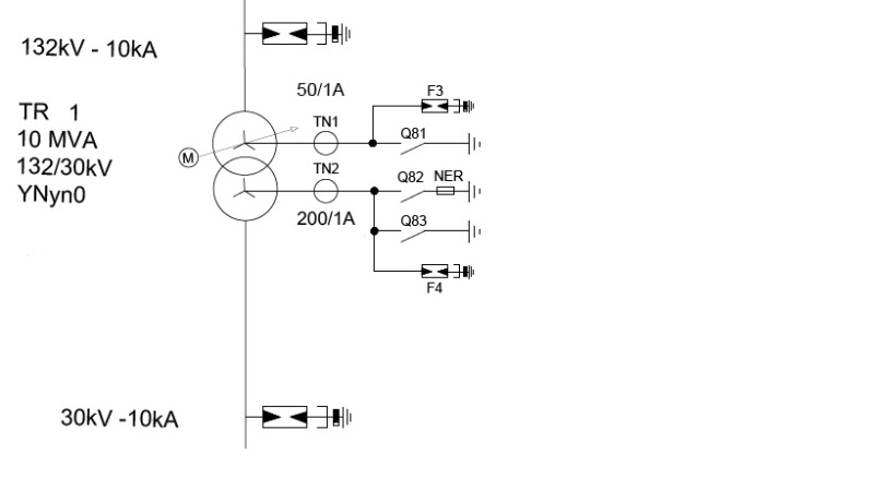
Untitled_zviyg5.jpg


the voltage rating for Q81 and TN1 shall be sufficient to withstand neutral voltage rise in case of Q81 is open and a fault upstream happens, which in the case of Q81 is open, will be 132/Sqrt(3) = 76.212 kV, this corresponds to a line-to-line rated equipment of 132 kV as well.

IEC 60076:3:2013 Annex D provides a formula to calculate the neutral equipment voltage ratings, but in this case the fault current will be ultimately zero as the zero sequence impedance is very high (neutral point float), thus, the full phase voltage is going to appear between neutral and ground, the surge arrestor is provided to avoid float voltage rise due to stray induction and to protect transformer neutral bushing.

In the SLD above, the consultant recommended using a 123 kV earthing switch, and in similar installations I have seen some recommendations going down to 80 kV?!

Any clue about neutral equipment voltage ratings? the need for disconnection at all?
 
Replies continue below

Recommended for you

A lot of messy questions of grounding design fall out of this one. Some systems are run ungrounded, with grounding switches only for testing and search for ground faults. If the 115kV ground switch is run open, the load will effectively seem the same as a delta from a 115kV load pespective. If either switch is run open, your 30kV loads need to be phase to phase only. If both switches are run closed, 115kV source sees 30kV ground faults. Most utilities do not want to see secondary ground faults, so running both switches closed may not be accpetable to the 115kV utility. If you run ungrounded, and a phase has a ground fault, and there is a ground reference on the system, it seems 80kV will suffice; the neutral voltage never rises above source phase to ground voltage. If remote source is ungrounded, all bets are off on what voltage you might see on a transient arcing fault. This is not a small matter you bring up.
 
Clear.

How 80 kV is derived in this case? IEC 60076:3 shows how to calcuate the neutral voltage with NGR, not with open neutral, however, the same equation with Zn = inf. yields that phase-to-ground voltage apprears on neutral to ground.

However, equipment like CT are specified with line-to-line voltage ratings, so it will be rated for a line-to-ground voltage of 115/Sqrt(3) i.e 115 kV Line-to-Line.

again, this is the system voltage, is my approach correct?

 
Not sure of the specifics of how 80kV is selected. I lack a copy of IEC 60076.
Not sure of what you are saying in some the above, but a switch on the neutral cannot see phase to phase voltages. Just phase to ground. In high impedance grounded system there is a long story of how arcing ground faults can create huge phase to ground votlages. That is too much to get into here. Maybe IEC 60076:3 will help.
However, ignoring the arcing ground fault concern, the switch would be reated for neutral voltage when there is phase to ground fault, which would be about Vn = 115/sqrt(3) * safety margin. Typical effective grounding says that if X1/R0 <1 and X0/X1 <3, then phase-ground overvoltage on unfaulted phases during ground fault is supposedly limited to ##%. Somewhere along the line I recall seeing a calc that said what the ##% number is, but I cannot put my finger on the matter; maybe someone else can. Another factor is a system is run nominally at 115kV but voltages are +/-10%. Your case it seems ## = 1.2. Seems within reason at least.
 
In my opinion, in the case of one phase-to-ground fault [let’s say R] and interrupted connection with the transformer the neutral potential will shift from 0 to VST/2[132/2=66 kV] and then the voltage between this neutral and ground will be:
Um=sqrt(132^2/4+132^2/3)=100.8 kV.
According to ABB High Voltage Surge Arresters Buyer´s Guide Ed. 9.2/2012
for non-effective earthing Uro=1.11*Um Uro=112 kV.[Table 2].
A surge arrester type PEXLIM P-X XN170 Ur=120 kV.
So, in my opinion, rated 123 kV of the neutral equipment it could be taken into consideration.
Neutral_rated_voltage_lpcdgz.jpg
 
Status
Not open for further replies.

Part and Inventory Search

Sponsor