Continue to Site

Eng-Tips is the largest engineering community on the Internet

Intelligent Work Forums for Engineering Professionals

  • Congratulations KootK on being selected by the Eng-Tips community for having the most helpful posts in the forums last week. Way to Go!

Transformer Saturation Margin 2

Status
Not open for further replies.

ZeroSeq

Electrical
Apr 17, 2014
84
Hello,

I have scoured my technical documents regarding transformers and have not been able to find an answer to the below question. I am wondering if anyone would have an answer or direction to the following:

For distribution transformers (~20-50MVA base), how close to the knee point is design operation (for example, power transformers of this size are typically sized such that design operation is 5% below the knee point as shown on the B-H curve)?

As the saturation curves are difficult or impossible to acquire for existing transformers, I am looking for a way to model the sat curves using a "typical" knee point, used in conjunction with estimated CRGO steel excitation characteristics.


Thank you
 
Replies continue below

Recommended for you

Generally today's transformers are designed at 1.7 T with the understanding it can work continuously at 110 % over fluxing (ie 1.9 T) and 125 % for one minute and 140 % for 5 sec. Complete saturation is assumed at around 1.98 T.
 
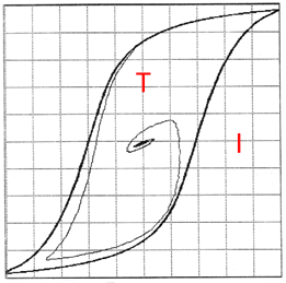
The general shape looks like this:

image_ospeia.png


Probably not new to you. But had that picture available. It is from a test with a switching off and demagnetizing the core by having a parallel capacitor so that the damped oscillation takes flux down to zero. Not calibrated, but prc's data seem to indicate that the flux density range is close to +/- 2 T.

This transformer was for demo purposes and is quite small. 850 VA.

It would be interesting to hear what prc says about the probable flux range.

Gunnar Englund
--------------------------------------
Half full - Half empty? I don't mind. It's what in it that counts.
 
prc, that is great info. I have read through the "list of standards relevant to transformers" document you compiled, and cannot find anything which would strictly quantify this. Would you happen to know if there are standards or recommended practices with respect to designing to those constraints (110%, 1.9T continuously)?
 
National standards are not specifying any limit on rated flux density. But there are many utilities who clearly mention that under 110 % continuous over fluxing, flux density in the core shall be less than 1.9 T . IEC 60076-1 General requirements of Power Transformers specify that at no-load, transformers shall be capable of operation at 10 % over fluxing and at full load 5 % over fluxing ( Clause 5.4.3)and under load rejection Generator transformers shall be capable of 1.4 times overvoltage for 5 seconds( Clause 5.3)
Nearly 40 years back, CEGB used to specify max B of 1.7 T for GTs, 1.65 T for interconnecting transformers and 1.55 T for sub transmission transformers. The reduction in B in later cases was for taking care of over fluxing due to tap changing. Very low sound level is specified for transformers for New York City and manufacturers may adopt 1.4 T or lower to achieve such silent operation. Before the oil shock of 1970s, GTs used to be made with a flux density as high as 1.8T. With todays high loss capitalization rates such high B are rare.
 
Status
Not open for further replies.

Part and Inventory Search

Sponsor