Continue to Site

Eng-Tips is the largest engineering community on the Internet

Intelligent Work Forums for Engineering Professionals

  • Congratulations IDS on being selected by the Eng-Tips community for having the most helpful posts in the forums last week. Way to Go!

Transformer Voltage Regulation

Status
Not open for further replies.
Replies continue below

Recommended for you

The voltage drop is due to the leakage reactance of the transformer along with the winding resistance. So %Z is the dominant factor but the X/R of the transformer as well as the power factor of the load also factor in since these are phasor quantities.

If you can measure the voltages, then the calculation probably doesn't matter much. Google should offer up some equations and phasor diagrams.
 
Google isn't being to helpful, unfortunately. Either that its the terms I'm searching lol.


I'm also hearing the %Z equals voltage regulation, but my understanding is that is heavily dependent on load power factor.
 
%Z is at short circuit conditions and X predominates. (X/R ratio).
Voltage regulation for a resistive load includes the resistance of the load as well as the resistance of the transformer.
Rated regulation is stated at a reasonable power factor.
The % regulation is less than the %Z.


Bill
--------------------
"Why not the best?"
Jimmy Carter
 
Thanks Waross. As I understand, power factor plays a significant role- a leading power factor may even raise voltage.


@DPC- Good to know, love the math in that PDF.
 
Best tutorial is in J&P Transformer Book or Transformer Engineering by Blume. First note from IIT is more accurate.
 
I have the 12th edition. Any section in particular on calculating regulation for a given power factor at various loading?


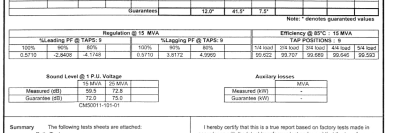
I have tests reports showing regulation for various transformers, but unsure how to mathematically obtain these results when impedance and X/R is known.

Test_report_regulation_y3mjdr.jpg
 
Voltage regulation=(V_nl-V_load)/V_load it seems to me o.k.
If we'll refer the voltage difference to the V_nl in this case voltage regulation is less than referred to V-load.
The rated voltage has to be for the rated plot[tap].
The rated current has to be for the rated voltage and rated apparent power.
In order to do a more accurate calculation we need the winding resistance then the copper losses.[ Perhaps we need the measurement temperature of wire and the actual temperature for calculation].
Since the power factor is not a rated value-except 1 for S-we may have a minimum, a maximum and an average regulation.
However, what I think IEEE 241/1990 3.6.1 General Mathematical Formulas where es=V_nl and er=V_load it will be enough.
 
Mbrooke,

You can do the exact same thing with voltage and current vectors and impedance drop to show how and why capacitor banks raise system voltage. The basic idea though is that imaginary lagging current causes the greatest magnitude voltaage drop across reactance due to it being in line the the voltage vector. Leading current causes a voltage rise across an inductor because it is inline with the voltage but in the opposite direction. Transmission lines show the same issue with the magnitude voltage drop being related to the PF of the power traveling along it.

So if someone ask why capacitors increase system voltage, you can tell them that it reduces the magnitude of the current needed deliver vars to the load and it reduces the amount of lagging current in the system and thereby reduces the voltage drop across the transmission line reactances.

------------------------------------------------------------------------------------------
If you can't explain it to a six year old, you don't understand it yourself.
 
Note: when you use the sums of the inductive reactances and the sums of the resistances to determine the voltage drop, you cannot use that figure directly to find the voltage drop under load.
You must use that figure and the no-load voltage to determine the voltage under load.
Then you subtract the load voltage from the no-load voltage to determine the regulation.
That's the simple explanation.
To repeat the calculations for an actual transformer, you must use the ffPF that the transformer is rated at to arrive at the load inductive reactance.
One method gives you the actual % regulation with a real load.
The other method gives you the rated % regulation of the transformer.
Both methods have valid uses and understanding both makes it easier to use the method that you need for your particular issue.

Bill
--------------------
"Why not the best?"
Jimmy Carter
 
Mbrook, J&P 12 th edition Please refer Section 1.6 under Transformer Theory.

% Regulation is always reported at 75C and change with temperature is negligible with temperature change, at least for medium and large transformers. This is because % R (Vr) is always very low (0.5 %-0.1% 20-1500 MVA ) compared to Vx (>8%)

% Regulation at unity power factor = Copper loss kWx100/ Rating in KVA + square of (percentage reactance)/200 ( the second term is prominent in this case)

% Regulation at any other power factor(angle phi) and part load ( 'a' pu of rated load) = a(Vr cos phi + Vx sin phi) + square of {a ( Vx cos phi-Vr cos phi )}/200.

Vr % = Copper loss (load loss ) kW x100 / Rating in KVA
Vx = Square root of ( square of percentage impedance -square of Vr)
 
Status
Not open for further replies.

Part and Inventory Search

Sponsor