Continue to Site

Eng-Tips is the largest engineering community on the Internet

Intelligent Work Forums for Engineering Professionals

  • Congratulations GregLocock on being selected by the Eng-Tips community for having the most helpful posts in the forums last week. Way to Go!

Transportation analysis by finite element

Status
Not open for further replies.

Sajjad2164

Mechanical
Dec 22, 2015
55
Hello, friends!
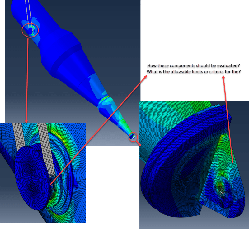
I am told to perform a finite element analysis for a transportation process of a special vessel. The model includes trunnions and a tailing lug. For the shell, I executed the linearization process and compare the results with allowable values given in ASME-SecII, Part D, but I am wondering what allowable limit should I use for the structural attachments such as the body of trunnion and tailing lugs? I appreciate any guides in the process.
Thanks
Engineering_Tips_jlynmn.png
 
Replies continue below

Recommended for you

Sajjad2164

ASME Sec VIII div 2 is silent about the transportation/erection load analysis of static equipment installed in onshore or offshore platform and its allowable and only considers transportation loads on operating vessels installed in ocean-going ships, barges, and other floating craft or used for motor vehicle or rail freight in Table 4.1.1 and Table 5.2

Following might help depending on where is the jurisdiction of vessel to be transported or erected.
- Pressure Vessel Design Manual by Dennis Moss
- DNVGL-ST-E273
- EN 13445-3

I am assuming you are not able to qualify the stresses as per ASME allowable.

My opinion- Use AMSE allowable stress first for qualification. If not qualified, go for AISC/Eurocode allowable for structural elements -Trunnion/Lifting lug/padeyes and ASME for shell (Junction-ASME). Even then its not qualifying, check whether you are using correct factors for transport loads. The last alternative would be Structural-AISC/Eurocode allowable stress for attached structure and shell (This will be somewhat difficult to convince to client/approver). If nothing works, then you need to add stiffeners or modify structural geometry to satisfy at least structural allowable.

Another easy option is to use limit analysis and find out the allowable capacity which must be greater than the expected loads without resorting to stress classification and allowable stress.

Hope this helps.
 
I am following the instructions recommended in AISC. I think Dennis Moss uses the same criteria as well. Now, I'm wondering if I should extract the forces (tensile, compression, bending, and shear) and then use hand calculation to obtain the corresponding stresses and compare them to the criteria of AISC.
 
Yes. But its ok if client/approver and you are on same page. And many clients/approver generally demand ASME allowable criteria for shell/junction (even though logically AISC/structural allowable stress is sufficient).

How much area of junction is above ASME allowable stresses? Why not limit FEA?

Note-In any case (FEA or Manual calculation), you need to qualify weld also using analytical calculation, if weld is other than full penetration.
 
Much as I would allow stresses greater than the ASME Sect II Part D allowables during the one-off hydrotest, I would also allow higher stresses during the one-off erection lift. When lifting the vessel is not a pressure vessel, but merely a structural member supporting it's own self-weight. Division 1 is based on a safety factor of 3.5, which is crazy for a lift.

We generally go a significant portion of yield for membrane, and a significant portion of tensile for surface. Basically, as long at there's no permanent deformation it's good. I do not recalling submitting stress calcs during lifting to an Owner, but if calcs were requested I stick to this. Hundreds of lifts says the limits are OK even if the customer didn't like them.

ASME B30.20, along with the matching BTH-1 (Below The Hook), is for rigging components, and addresses designing for thousands of lift cycles. Probably too conservative but I believe BTH-1 has info on lug design for your bottom tailing lug if you find nothing else.

Hard to tell scale from your screenshots, but the vessel looks large enough that I'd only use a small impact factor (10% ??) as the crane operation should be very well controlled on this big a lift.

Looks like multiple pads on the trunnion (my apology if I've misunderstood the screenshot). Expensive. Just use a larger pipe size to distribute the load into the vessel.
 
Status
Not open for further replies.

Part and Inventory Search

Sponsor