Continue to Site

Eng-Tips is the largest engineering community on the Internet

Intelligent Work Forums for Engineering Professionals

  • Congratulations KootK on being selected by the Eng-Tips community for having the most helpful posts in the forums last week. Way to Go!

Transverse Loading Positions for Max Live Load Effects in Pier Cap

Status
Not open for further replies.

Son of a Bridge

Structural
May 12, 2019
18
Hello everyone,

I am trying to understand how a truck and lane load are positioned transversely along a bridge for one-lane loaded, two-lanes loaded, three, etc.

As per AASHTO, "Both the design lanes and the 10 ft loaded width in each lane shall be positioned to produce extreme force effects. The design truck or tandem shall be positioned transversely such that the center of any wheel load is not closer than 2 ft from the edge of the design lane (for design of all other components, except the deck overhang)".

I will attach a PDF of what my interpretation of the code is. Could someone please tell me if my intuition is correct?

Also, what is an easier way to determine the controlling live load case (for a pier cap) based on the transverse positioning of the design truck/tandem and lane load?

Any help is appreciated. Feel free to provide any hand calculations examples.

Thanks
 
 https://files.engineering.com/getfile.aspx?folder=f4869c8d-ccda-4486-88d6-9f855aaf4256&file=Example.pdf
Replies continue below

Recommended for you

@retired13,

The sketch only shows one particular case. I'm interested in understanding how the design truck/tandem and lane load are positioned transversely for multiple cases (one lane, two lanes, etc).

The PDF I attached in the original post is how I think the design truck/tandem and lane load should be positioned (for two lanes). Not sure if my interpretation of AASHTO is correct. Could you please verify?

Also, I will attach another PDF from WisDOT. I used it as an example to create the first PDF.

Seems like FHWA didn't provide any limitations in that sketch (e.g. 2' min distance between edge of design lane to center of any wheel).

Any help is appreciated.

Thanks,

 
 https://files.engineering.com/getfile.aspx?folder=e729f5af-5555-4a29-acdd-9be7961b2c19&file=WisDOT.pdf
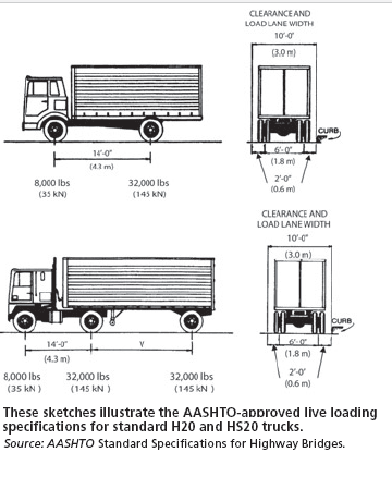
The truck width is fixed at 10', and the wheels are 6' apart, so when position two trucks, the wheels can get as close as 4'. I don't think you have problem with lane load.
 
@retired13

Can the axles move between the 10' loaded lane (1', 6', 3') or do the axles have to be centered within the 10' loaded lane (2', 6', 2')?
 
The 10' wide truck (body) can be placed at any location in the 12' traffic lane, but the truck bodies can't overlap. The wheels are fixed to the truck body, so they follow the truck position, the most close position of two trucks' wheels, therefore, is 2'+2' = 4'. Make sense?
 
Yes, it makes sense now.

I didn't know the 10' loaded width was the truck body attached to the 6' axles.

Originally I thought the 6' axles could move within the 10' loaded width, but i guess i was wrong.

Thank you for the clarification.

 
You are welcome. I've sensed that. Note that for multiple traffic lanes, the most critical condition for interior girder is not necessarily with all lanes occupied by trucks, it could be produced by fewer trucks with wheels directly/close on one of the girder.
 
How large is the Pier cap and how many bearings do you have? I find its best to use a software like RC pier or some other analysis software to run all the lateral steeps for the load cases and envelope the max load effects. With experience you can learn which positions control and simplify your analysis by hand but if you don't have experience you need to look at them all.

The problem is that as you move the vehicle you get a reaction at one bearing that is based on the AASHTO distribution factors and multiple presence factors. You also need concurrent reactions at the other bearings or you risk over designing.
 
Download the RC-Pier user manual. There is a section on the "theory" and they have lots of examples on pier live loading.

One of the biggest things I used to have trouble teaching young engineers is that the live load rules are different for substructures. You can't maximize the girder reactions at the same time. I've seen way too many bridge abutments and piers over-designed in my career because designers often, and incorrectly, just take the superstructure reactions and apply them to the foundation designs.

I know because I did it too when I was first learning!
 
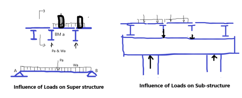
I think the difference between arranging traffic loads for super structure and sub-structure can be expressed as follow:

Supper Structure - Bridge Girder
- So arranged to produce the maximum load to be carried by a "single girder" in the longitudinal direction (see sketch).

Sub-structure - Pier, Abutment
- So arranged to produce the maximum load (P) and/or effects (M, V, T) to be resisted by the element under design.

Hope the above helps, though more elaboration/example is required, especially concerns for the substructure.

t_v4oupu.png
 
Where are BridgeSmith and bridgebuster? I wonder whereabout of these two bridge experts (design and construction/inspection).
 
I know you are designing a pier cap but something to consider is that at some point, the 1.33x impact factor goes away for some substructure components.
 
@retired13

Yes, I plan on doing hand calculations to determine the controlling live load case.

I also agree on the difference when designing the superstructure and substructure for live load (transversely). Believe it or not, that picture explains it in a simple manner. I guess the saying is true "a picture is worth a 1000 words".

@MIKE_311

For the example im working on, the pier cap is about 30' long. Im creating hand calculations to make sure I understand the concept correctly. I'm sure it will help in the future. It may take a while, but i'll get there eventually. I plan on doing spot checks here and there. Not necessarily checking multiple limit states. Just a few to grasp the concept. Analysis is essentially the same. Im not sure if to use the moment distribution method for frame analysis or stiffness method (matrices). I dont plan on using a continuous beam with knife edge supports since the column heights may vary (different pier/column stiffness in-plane and out-of-plane).

And yes, for TxDOT we do not consider impact when designing the foundation as stated in the TxDOT Bridge Design Manual.

@TheRick109

Yes, in the end I plan on comparing my results with rcpier. I've looked into the user manual before. At first I thought the axles could move within the 10' loaded lane, but I guess that's not the case as stated in the previous post. I also read in a textbook that engineers should not use the live load reactions from the girder design since its unrealistic (and extremely conservative) for each girder to be maxed out. But its true, ive seen many hand calculations where engineers use the live load reactions from the girder design to design the pier cap
 
Glad that my cartoon worked :) Have fun to join the bridge world!
 
Where are BridgeSmith and bridgebuster?

I haven't been logging in as much since I got booted from the Pub. Not as much to keep my interest without that.

I know you are designing a pier cap but something to consider is that at some point, the 1.33x impact factor goes away for some substructure components.

Generally, impact is applied to steel and concrete components above the ground. Elastomeric bearings do not need to be designed for impact.

I think the difference between arranging traffic loads for super structure and sub-structure can be expressed as follow:

Supper Structure - Bridge Girder
- So arranged to produce the maximum load to be carried by a "single girder" in the longitudinal direction (see sketch).

Sub-structure - Pier, Abutment
- So arranged to produce the maximum load (P) and/or effects (M, V, T) to be resisted by the element under design.

Hope the above helps, though more elaboration/example is required, especially concerns for the substructure.

I think that's right. Anyway, in practical terms what we do is take a reaction at the pier for one girder and divide by the distribution factor, to get the reaction due to an axle line (the combined reaction due to a line of vehicles in one lane on the bridge, per the AASHTO loading), and then divide by 2 to get the wheel line reaction. That's magnitude of the point load we apply to each of the load positions we're combining.

Rod Smith, P.E., The artist formerly known as HotRod10
 
Glad to see you back, with, or without mug :)
 
Didn't look in detail here. How's come you are using truck body width a 10 feet when the legal limit is 8-1/2 feet?
 
AASHTO standard truck to be placed in 12' wide drive lane.

t_z7yapf.png
 
Status
Not open for further replies.

Part and Inventory Search

Sponsor