Midwayman
Electrical
- Jul 15, 2022
- 6
Hello to all,
Over the last year, I have been trying to educate myself on a proper foundation for a steel building I want to build. I wanted to share the design as it sits to see if if there any gross oversights, and to ask a few questions.
The building is all steel (open-web welded trusses, steel girts, steel purlins), 50' (endwall) x80' (sidewall) , with a full mezzanine (bar joist supports on the steel trusses). Bay spacing is 13' and 14'. The trusses are built to potentially support a 12' lean-to on either side at some later date.
Soil is clay and the building will be on a slope (about 4' of drop across the 50' endwall). After some deliberation, it seemed the best measure to go with a frost depth (36") trench footing, with a 54' stem wall on top built from ICFs. At each truss location, a pilaster would be built. I planned to mount the endwall columns on top of the wall (no pilaster).
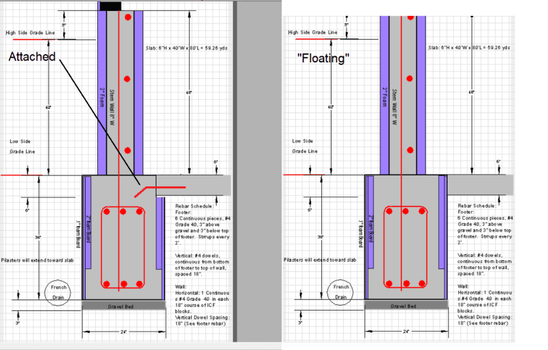
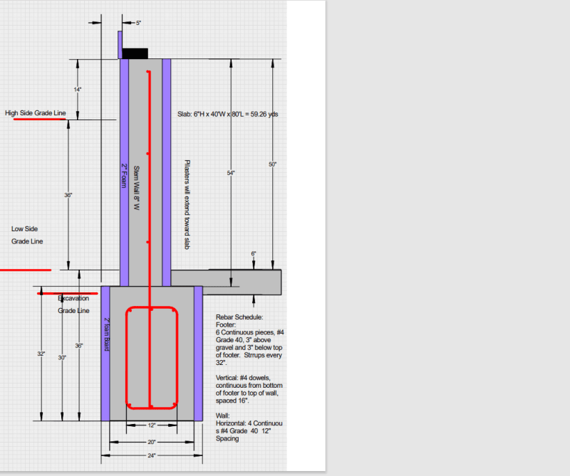
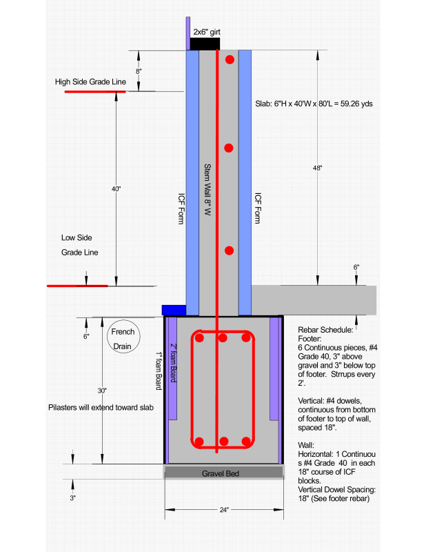
Here is a drawing of the foundation cross section for the footer and wall:
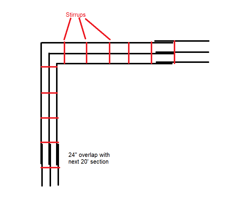
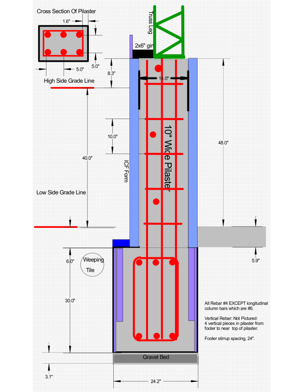
The pilasters which would reside at the base of each truss:
So here are some questions I have:
[ol 1]
[li]Is it a concern that the center of the ICF perimeter wall is toward the outside of the footer, while the pilaster extends in to the very edge of the pilaster. I had a hard time tracking down definitive rules for how these should be centered on a footer.[/li]
[li]Is the fact that the building will be supported by a pilaster/wall with a cold joint to the footer (right at grade in some cases) a concern with respect to the non-axial forces from the truss leg?[/li]
[li]You will notice the use of foam on the sides of the trench footing. Is this acceptable? Does it need to be of any specific PSI rating?
[/li]
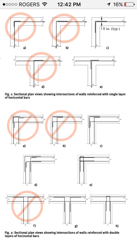
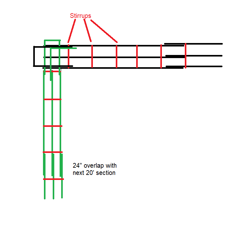
[li]I happened across a significant number of pre-made grade 60 #4 stirrups that are 12" wide by 30" tall. The width seems about right, but the height would violate the 3" cover rule if I kept the footer at 30" deep. Then I came across an article discussing the advantages of angled stirrups Link which if I angled (@53°) would fit perfectly . However, in reading, this almost seemed more appropriate for suspended beams for overpasses than in a footer.
a. Is angling the stirrups beneficial or detrimental in this instance?
b. If not, would there be an advantage to making the trench footer 36" deep (using 6" forms above grade) and letting the slab pour against the footer instead of between the ICF walls?[/li]
[/ol]
I appreciate any help with answering these questions, or general suggestions you may have.
Best Regards,
Midwayman
Over the last year, I have been trying to educate myself on a proper foundation for a steel building I want to build. I wanted to share the design as it sits to see if if there any gross oversights, and to ask a few questions.
The building is all steel (open-web welded trusses, steel girts, steel purlins), 50' (endwall) x80' (sidewall) , with a full mezzanine (bar joist supports on the steel trusses). Bay spacing is 13' and 14'. The trusses are built to potentially support a 12' lean-to on either side at some later date.
Soil is clay and the building will be on a slope (about 4' of drop across the 50' endwall). After some deliberation, it seemed the best measure to go with a frost depth (36") trench footing, with a 54' stem wall on top built from ICFs. At each truss location, a pilaster would be built. I planned to mount the endwall columns on top of the wall (no pilaster).
Here is a drawing of the foundation cross section for the footer and wall:
The pilasters which would reside at the base of each truss:
So here are some questions I have:
[ol 1]
[li]Is it a concern that the center of the ICF perimeter wall is toward the outside of the footer, while the pilaster extends in to the very edge of the pilaster. I had a hard time tracking down definitive rules for how these should be centered on a footer.[/li]
[li]Is the fact that the building will be supported by a pilaster/wall with a cold joint to the footer (right at grade in some cases) a concern with respect to the non-axial forces from the truss leg?[/li]
[li]You will notice the use of foam on the sides of the trench footing. Is this acceptable? Does it need to be of any specific PSI rating?
[/li]
[li]I happened across a significant number of pre-made grade 60 #4 stirrups that are 12" wide by 30" tall. The width seems about right, but the height would violate the 3" cover rule if I kept the footer at 30" deep. Then I came across an article discussing the advantages of angled stirrups Link which if I angled (@53°) would fit perfectly . However, in reading, this almost seemed more appropriate for suspended beams for overpasses than in a footer.
a. Is angling the stirrups beneficial or detrimental in this instance?
b. If not, would there be an advantage to making the trench footer 36" deep (using 6" forms above grade) and letting the slab pour against the footer instead of between the ICF walls?[/li]
[/ol]
I appreciate any help with answering these questions, or general suggestions you may have.
Best Regards,
Midwayman