Continue to Site

Eng-Tips is the largest engineering community on the Internet

Intelligent Work Forums for Engineering Professionals

  • Congratulations GregLocock on being selected by the Eng-Tips community for having the most helpful posts in the forums last week. Way to Go!

Trench shoring design 2

Status
Not open for further replies.

SoilGuy89

Civil/Environmental
Oct 11, 2014
3
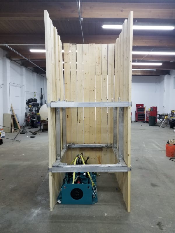
Looking for a little input on a temporary shoring design. They went ahead and built the system they want to use, but didn't do any calcs to back it up. What's the best approach for checking the stresses in the aluminum members? For what it is, I'm sure there is enough capacity, but just need a calc to support it.
Trench_image_xvenmr.jpg
 
Replies continue below

Recommended for you

I'd want a laboratory supervised load test and report signed by a PE to show the failure loads that can be applied to the struts with pinned connections. Same goes for the horizontal members. Struts should be pre-bent say 1/20th of span. As to what loads to take for design, I'd apply a significant safety factor to straight un-bent to allow for unexpected job loadings such as equipment and personnel weights on the struts and some actual bending of them. Bent test result should not be exceeded by working loads. The wood sheeting on the job might be significantly different than what the model has. A summary report might cover the minimum wood sheeting strengths recommended, but suggest limits as to depths of use assuming soil density of 1.0 times on-site typical densities, fully saturated. Any local codes also should be shown as covered by the set-up proposed.
 
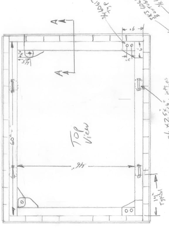
Would it be possible to model the frame using a 3D structural program? All of the aluminum members are 3”x3”x0.25” I attached a sketch looking down from the top.

BA8AEBDC-3BBF-4406-A8B8-0C53E38054D0_rdtvuo.jpg
 
A few questions.

Is it expected that sheeting will be required on one end or is that an options?

When this is removed or moved will the computations throw in a point load where the back-hoe pulls it free?

What limit might there be for that pull in case of cave-in or other heavy resistance?

Any restrictions as to where the pull can't be applied?

Can the corners be other than 90 degrees?

A common design for these allows lifting or placing them so that one side of the trench braces can be lifted to partly collapse. Can that be done with this?

Has this plan been run by any excavating foremen?
 
SoilGuy89 said:
What's the best approach for checking the stresses in the aluminum members?
All of the aluminum members are 3”x3”x0.25”
Would it be possible to model the frame using a 3D structural program?

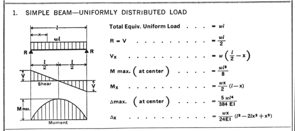
To get the bending moment, check the longest member (60") as a simply supported beam with a uniformly distributed load. Then calculate maximum bending stress. The beam will probably be fine for most practical loads, it's span (60") to depth (3") ratio = 20:1 is reasonable.

SimpleBeam-UDL-1_fmsqog.png


The hard part is determine the uniform distributed load applied to the beam. You will need to know both soil properties and how the shoring is used. At best the applied load will be a SWAG.
Also, check the to see if stress in the lumber is acceptable.

IMHO, put the software aside, all it will do is give precise answers to a question that is inherently approximate.


[idea]
[r2d2]
 
When this OG was a kid in the 1930's the WPA program put a lot of people to work digging trenches for sanitary sewer systems. Work was done by hand and the sheeting was driven by hand. For the deep trenches that meant long sheeting. In order to go from say 8 foot depth to 16 foot depth the boards had to be pretty long, say 12 feet at least. After a 6 foot trench was dug they started to drive the sheets and followed along with digg8ing by hand. High saw horse supported platforms gave a place to stand to pound the sheets with big sledge hammers. Perhaps due to that difficulty of pounding wood planks there doesn't seem to be much of any use for wood sheets any more.
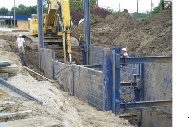
Take this job where progressive deepening can be done by sections of sheeting follows the job down.
Trench_brace_dfkycz.jpg
 
what you are showing is a slide rail system. very expensive, very good but in general is not used unless you either have very bad ground conditions such as wet, running sand or adjacent structures or underground pipes that cannot tolerate any settlement. In about 35 years, I have used these on one project and it was to protect a high pressure gas line.

24loojc.jpg
 
My view of "home built" bracing is maybe OK for that simple sewer root problem in the front yard, but why? Rental places have all you need and some provide training so there is no safety risk left uncovered. It's like inventing the wheel.
 
Status
Not open for further replies.

Part and Inventory Search

Sponsor