dgallup
Automotive
- May 9, 2003
- 4,715
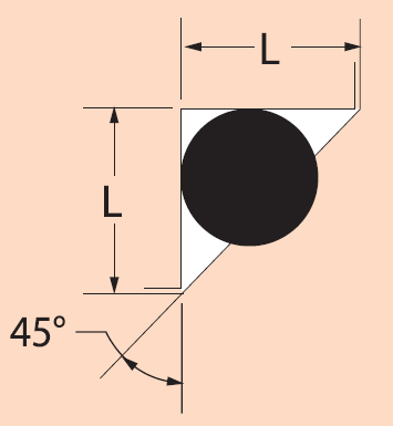
We have a part that uses a triangular o-ring groove similar to what is shown in Parker O-ring Handbook design chart 4-6 on page 4-21. We have been using this particular design for over 5 years without problems. There seems to be some change in manufacturing process as this seal has worked quite well but we have not found anything out of spec so far. The o-ring is a 70 durometer fluorosilicone material in an oddball size. I've compared the groove fill to the Parker dimensions and we are quite close. The Parker sizes above and below ours are nominally 90.2% and 90.9% groove fill and ours is 89.5% so just a little lower.
This seal gets leak checked a number of times, once in an outlet pressure rise automated test in production of short duration, ~ 6 seconds. Second in a visual submerged bubble leak test also of ~6 seconds. Both of these apply 9 bar differential pressure to the seal. If the parts come to engineering we do a much longer leak test with a flow meter at 14 bar differential, about 60 seconds. Our customer assembles 4 to 10 of our product into a larger assembly and does a pressure decay test at 9 bar differential for about 5 seconds. Our customer's customer does a finished system test that is much longer.
Recently, occasionally (maybe 0.1% of the time) one of these seals that has passed multiple short leak tests will start to leak at the end customer after a couple of minutes. We use the same o-ring material in 4 radial seals in this product and I have never seen one of them display this time dependent failure mode. I'm trying to understand what is going on internally in the triangular o-ring groove that allows this to happen.
My thought is that the pressurized o-ring initially takes a shape inside the triangular groove with approximately equal radii in each of the three corners but as pressure is applied it gradually creeps down so the low pressure corners have very small radii and the high pressure corner has a much bigger radii. Eventually the contact with one of sides with the pressure differential is lost.
It's hard to understand as when we certified this product there were 3 minute leak observations at -40C, room temp and +120C and we never saw this behavior and we do periodic confirmation of production tests as well.
----------------------------------------
The Help for this program was created in Windows Help format, which depends on a feature that isn't included in this version of Windows.