Continue to Site

Eng-Tips is the largest engineering community on the Internet

Intelligent Work Forums for Engineering Professionals

  • Congratulations waross on being selected by the Eng-Tips community for having the most helpful posts in the forums last week. Way to Go!

Tributary area formula

Status
Not open for further replies.

DSNOW

Structural
Apr 2, 2019
1
4D340F91-63B5-42C9-A308-555C878064F1_xozfyq.jpg
4EC81506-68F0-46FA-A8F1-912F7847B8B3_x2o8ve.jpg


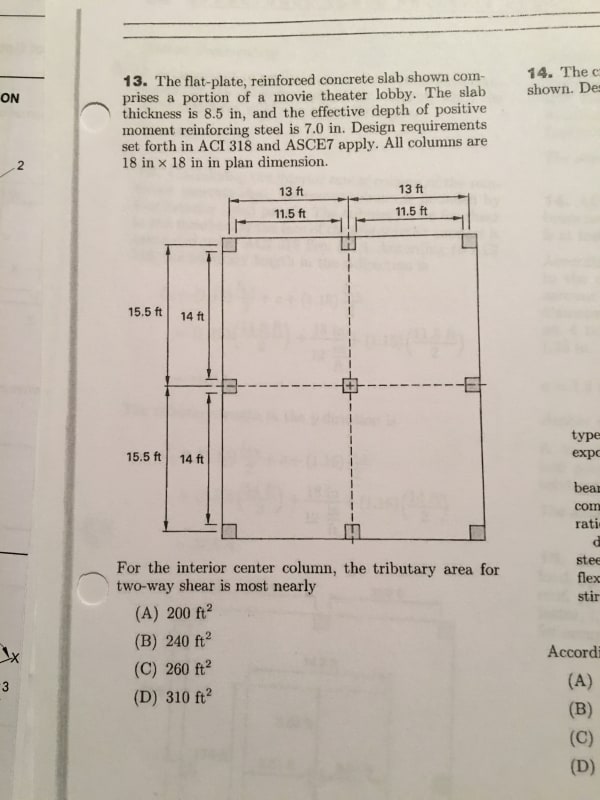
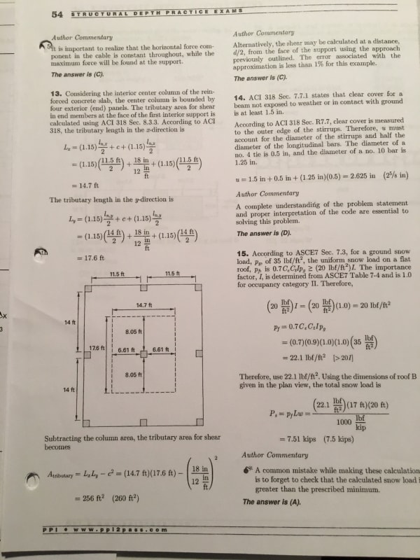
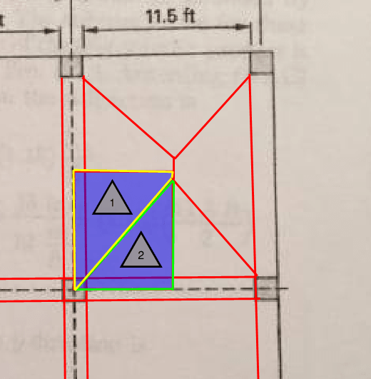
I am currently studying for the P.E. and I’m working an old practice test. Can someone please explain where the formula for the length in the X and Y came from? I understand the tributary area is the area the column is supporting but I don’t understand the 15% increase in area. I have looked through ACI318-14 and didn’t see this equation anywhere. Any help would be greatly appreciated.
 
Replies continue below

Recommended for you

The 15% increase is to allow for continuity in each direction. This is a long established approximation for collecting column loads in multispan continuous beam systems. For a two span condition as in the example, it really should be more, as the centre reaction is 5/8 of the total load.
 
It's due to the continuity of the beams, central reaction for pin ended double span with constant load width is 1.25wL for example. Throw in some continuity at exterior and two way beam and this reduces obviously.

As to where they got this in ACI I cannot tell, but my own local code based on ACI has a simplified method for the assessment of moment and shear that boils down to using coefficients like the 1.15 noted. Have a look in ACI at these simplified methods for slab and beam design and it may be in there.
 
Refer to Section 8.3.3 (ACI 318-11). This is basically because of 2 end span condition where the shear at the exterior face of interior column is increased by 15%.

[Edit] - Looks like 3 responses crossed cyber space.
 
Ok found it in ACI318-14, refer to table 6.5.2 (similar to what slickdeals noted above.
 
I concur with what was said above with the only caveat being the table in ACI 318-14 is 6.5.4.
 
You guys are giving me flashbacks.....I remember this question and I don't like it at all.

The problem statement says "....comprises a PORTION of a movie theater lobby...," which makes me think that they are ALL interior columns.

Additionally, table 6.5.4 applies to shears in 1 way slabs and the problem statement says "two-way shear"
 
However in terms of the load and hence the tributary area it makes no difference if the slab spans one way or two way, the columns tributary area is the same.
 
A 1 way slab has to be designed for 1 way shear (beam shear) and 2 way shear (punching shear).

A 2 way slab also has to be designed for 1 way shear (beam shear) and 2 way shear (punching shear).

It also does make a difference if the slab is 1 way or 2 way. If it was 1 way, you'd only multiply one direction by 1.15. If it was two way, you multiply both clear spans by 1.15.
 
No I don't think so, because the total load supported by the column is the same, agree for the slab/beams themselves the actions are quite different for 1/2 way spans, but the question is about the column tributary area (i.e. total load carried by the column is similar, its just quarter vs half the load comes in from each beam). Happy to be proved otherwise via some analysis. Remember its only an estimate, they ask for the nearest value to the true value.
 
In response to agent and Cal..

I agree with cal in that you would only multiply 1 direction by 1.15.. in this case.

I dont see how this could work with a one way slab.. you would need beams to support the slab at locations that dont have a column. The flat plat 2 way slab spans from column to column in all directions.

So basically, I dont think you can ask this if the slab is one way.

If there was a beam spanning continuous over the center column, and the beam supported a one way slab, then yes, you'd multiply each trib width by 1.15

-MMARLOW EIT
 
I think its confused by the fact they don't show beams at the exterior edge but they don't show then either internally. I don't really understand what you mean by 'you would need beams to support the slab at locations that dont have a column.'. But irrespective consider the markup/explaination below

See below, irrespective if one or two way system, you are still multiplying each clear span direction by the 1.15 factor (if its a beam or a slab its the same, the two tributary areas 1 & 2 add up to the plan area as if it was a one way system even if two way. If one way then you are multiplying one direction as a continuous internal slab, and the other as a continuous internal beam case.

Capture_uc2bhu.png
 
Agent,

Yeah, I didn't really word it well. Basically, I'm saying what you sketched above would require that the trib width in both directions be multiplied by 1.15.

However, if there are no internal beams, the slab must be two way.

-MMARLOW EIT
 
Yeah, the solution did multiply both directions by the 1.15 factor as you've assumed.
 
Definitely both directions by 1.15 in all cases.

One way or 2 way, you still get moment shear. Statics is hard to argue against!

But the actual number has to be dependent on relative span lengths. If span length ratio is more than about 1.2, 1.15 could vary significantly.
 
These memories bring back memories of PTSD... post tensioned slab design.

Mike McCann, PE, SE (WA)


Status
Not open for further replies.

Part and Inventory Search

Sponsor