Continue to Site

Eng-Tips is the largest engineering community on the Internet

Intelligent Work Forums for Engineering Professionals

  • Congratulations SDETERS on being selected by the Eng-Tips community for having the most helpful posts in the forums last week. Way to Go!

True geometric counterpart for a CF cylinder.

Status
Not open for further replies.

Rwelch9

Mechanical
Apr 22, 2020
116
20200627_204246_1_nkqq5u.jpg


Hi

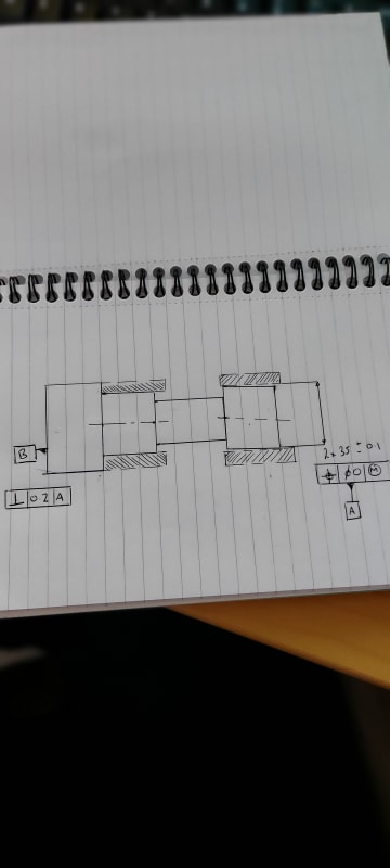
Please find attached sketch ,

The sketch is simply to illustrate a 2x cylindrical shaft diameter as a common datum.

My question , as most of you guys are aware my experience with true geometric counterparts is limited. ( due to most of my inspection experience is on a CMM )

As this is a 2x will the geometric counter part be like a bush that would touch an mate against the most outer points of the two cylinders ?

I have done the sketch to show a potential issue where by machining flaws or another reason the front shaft diameter is slightly tapered to the other one.

I am trying to understand if this scenario happened or the front cylinder axis was just 0.04 off center , how does this affect the geometric counter part to derive a common axis between the two cylinders .


Thanks
 
Replies continue below

Recommended for you

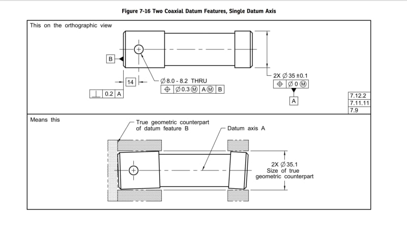
The standard shows it in a very similar way as you did.
Screenshot_20200628-071044_Drive_ib4fp2.jpg


The only thing which is alarming in your sketch is how the flat shoulder on the left is supported against the true geometric counterpart simulator. You have to make sure it doesn't constrain any degrees of freedom instead of the two cylindrical features, otherwise what you may be inspecting is parallelism to that shoulder instead of the intended perpendicularity.
 
Burunduk

2X and CF are same meaning? i.e, to be treated as single feature?
 
2X in conjunction with position within zero at MMC, datumless, applied on two coaxial cylinders with the same size dimension and tolerance, is equivalent to CF.
 
Burunduk,

With a part like either my sketch or from the standard , would the true geometric counterpart be 1 from each cylinder or just 1 that would touch the outer edges of the two cylinders together.

I have a part that basically the front cylinder is slightly tapered to the back cylinder , I am trying to work out what that would do with regards to the true geometric counter part and where exactly Datum A axis would derive from.

I ask only because I check parts on a CMM ( customer requirements ) so i try recreate this virtually as best i can to the letter of the book.

Thanks

R
 
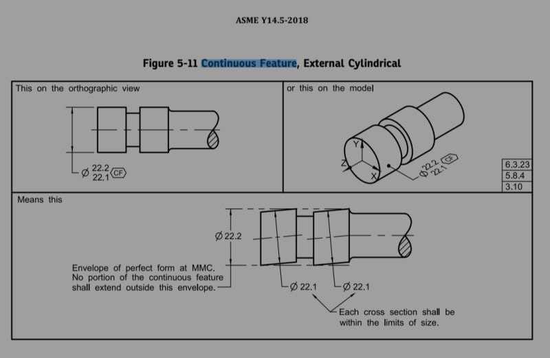
I think below image from ASME Y14.5:2018 may be referred.

IMG_20200628_122626_rbe8ed.jpg
 
Burunduk

How to inspect the part?

With single cylinder of dia 22.2 or two cylinder of dia 22.2 placed coaxially?
 
Sa-Ro,
As you can see in the means this portion of the figure you posted both cylinders are evaluated to a single 22.2 envelope of perfect form at MMC. When inspecting the requirement, a single gage should be used unless perhaps there is some technical difficulty. Using 2 coaxial gage cylinders will introduce some measurement error, because of coaxiality inaccuracy.
 
Burunduk

I am still trying to get complete understanding of this concept.

The figure you showed from the standard , Datum axis A is derived from the simulator.

As I have previously stated my CMM software I am creating constructed axis between the two cylinders to create a common axis. I am not convinced the software is accurately creating the true Datum Axis A as it would if I were to use a true geometric counter part.

So if you have a geometric counter placed against any highest points of the two coaxial cylinders . The axis of this geomteric counter would be the datum ?


Again referring to your post with the drawing from the standard. The means this portion .

Both datum feature cylinders Axis are completely off to the middle cylinder axis

Though using the geometric counter part and using this axis, it looks completely coaxial to the middle cylinder. This confuses me I must admit .

Any help on this would be greatly appreciated

Thanks

R
 
Rwelch9 said:
So if you have a geometric counter placed against any highest points of the two coaxial cylinders . The axis of this geomteric counter would be the datum ?

Yes. The datum axis is always the axis of the "true geometric counterpart" or as I am more used to call it because I'm working with the 2009 version of the standard - "datum feature simulator". If the datum reference is regardless material boundary (no modifier near the datum letter in the feature control frame) there is coincidence between the axis of the datum feature simulator and either the axis of the unrelated actual mating envelope of the feature (for a primary datum feature) or the axis of the related actual mating envelope (for secondary or tertiary). In your case, the datum feature is a pattern referenced at maximum material boundary - in this case (because of RMB), the datum axis may not be congruent at all with the axis of the related or unrelated actual mating envelope, because there is shift allowed between the datum feature and the datum feature simulator from which the datum axis is derived.

I truly don't know how much all this can help you with the CMM.
Are you also producing the parts or just measuring them?
If there is an option to potentially reject some good parts in favor of easier inspection with CMM, consider treating it as a datum feature referenced RMB.


In your case, the datum feature is referenced regardless material boundary (RMB).
RMB is a more stringent requirement than MMB (like RFS is more stringent than MMC) so you are not expected to approve any bad parts. For RMB you would have to simply use the high points on both cylinders to simulate two coaxial mating envelopes that contact those high points on both cylinders without one cylinder getting any priority (tighter connection with the simulator) than the other.
 
Rwelch9,
My apologies, I missed the fact that your datum feature A is referenced regardless material boundary in the perp. FCF.

I now modified my previous response according to that.
 
RWelch9,

Here are a few thoughts.

Your drawing specifies 2X and a position tolerance on the OD's. This means that:

-The two OD's are treated as two distinct features.
-When labeled as a datum feature, this creates a multiple datum feature (2009) or a common datum feature (2018).
-For the RMB datum feature reference, there would be two cylindrical simulators/TGC's that are fixed in location relative to one another (i.e. coaxial in this case).
-In 2009, "The datum feature simulators shall expand or contract simultaneously from their MMB to their LMB until the datum feature simulators make maximum possible contact with the extremities of the datum feature(s)."
-In 2018, "The true geometric counterparts shall expand or contract simultaneously from their worst-case material boundary to their LMB until the true geometric counterparts make maximum possible contact with the extremities of the datum feature(s). When irregularities on the feature(s) may allow the part to be unstable, a single solution shall be defined to constrain the part."

If the drawing had specified <CF> instead, then it would mean:

-The two OD's would be treated as one "continuous" feature.
-For the RMB datum feature reference, there would be one cylindrical simulator/TGC.
-The simulator/TGC is the smallest circumscribed perfect cylinder that makes maximum possible contact with the datum feature surface

The two OD's in your drawing have the same nominal size and size tolerance. This avoids additional cans of worms that we would have to open if they did not.


Evan Janeshewski

Axymetrix Quality Engineering Inc.
 
axym said:
This avoids additional cans of worms that we would have to open if they did not.

Evan,

Can we open those cans of worm, please?

Are you talking about this discussion? See thread below:

I am trying to learn something here.....

So, are you thinking that the second scheme, (coaxial features with different size diameters) is not valid within Y14.5 ?
I would like to know what are you thinking about that second scheme....
Thank you very much Evan.
 
greenimi,

The issue that I see is interpreting the statement "the datum feature simulators shall expand or contract simultaneously from their MMB to their LMB", if the difference between the MMB and LMB is different for each datum feature. If the simulators start at their MMB's and progress at the same rate, they won't reach their LMB's at the same time.

Evan Janeshewski

Axymetrix Quality Engineering Inc.
 
In real life, no mating parts act per that description.
 
Evan,

But in the second scheme datum feature is MMB (not RMB), so I don't think the statement of "the datum feature simulators shall expand or contract simultaneously from their MMB to their LMB" has anything to do with what I am asking.
Could you, please provide more details?

Basically, I am asking why the datum structure in the second scheme would NOT produce equivalent results?

copy-paste:
"Otherwise stated if datum A is referenced as = A-B
and
datum B is referenced as A-B
are those two datum schemes equivalent with the OP's second case?


greenimi,

I think we're talking about two different things now.

I will reply to the A-B question in the other thread.

Evan Janeshewski

Axymetrix Quality Engineering Inc.
 
Axym

Sorry I am slightly confused, So 100% this would be two separate TGC.

My question regardless of if i use physical counterparts or virtual on the CMM.

At what point of the the two cylinder axis to you create the common datum.

Thanks

R
 
Status
Not open for further replies.

Part and Inventory Search

Sponsor