Continue to Site

Eng-Tips is the largest engineering community on the Internet

Intelligent Work Forums for Engineering Professionals

  • Congratulations LittleInch on being selected by the Eng-Tips community for having the most helpful posts in the forums last week. Way to Go!

True position of a slot 3

Status
Not open for further replies.

Rwelch9

Mechanical
Apr 22, 2020
116
IMG_20200624_075944_bc4cbf.jpg


Hi

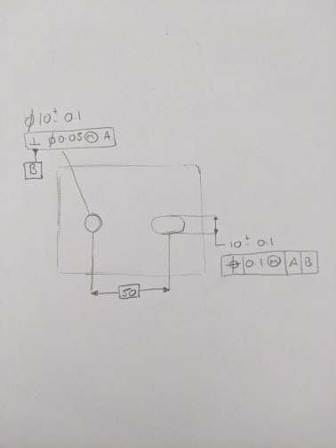
Please see attached quick sketch ,

Datum A would be one of the planes ( not shown )

Regarding the positional call out for the slot .

What would be the best way to think about / understand the basic dimension of 50mm.

It looks like a centre axis between the two radii, Although i hope i would be correct in saying Datum Feature would be the mid plane derived from the two small planes on the slot


Thanks

R
 
Replies continue below

Recommended for you

You are not controlling the location of the slot in the horizontal direction.

The ASME Y14.5 standards gives the exact interpretation of that condition; what do you think based on what is in the standard?
 
"What would be the best way to think about / understand the basic dimension of 50mm."

The true position of the longitudinal center of the slot (center of the geometrical theoretical geometry). By the way, the location of the slot is not defined in the direction of the 50 basic, the position tolerance you show doesn't control that.
 
3DDave + Burunduk

Thanks for your replies ,


I was completely unsure why the 50mm basic is placed .

The position of the slot in relationship of the hole , what is the best way show this on the drawing ,

If this was two holes , yes the 50mm basic would make sense to me ,

Thanks

R
 
50 basic should be there. You need another position FCF to control the slot's location in the direction of 50 basic.
 
See figure number something in ASME Y14.5-something.
 
Burunduk

I understand now about the two FCF placed on to the slot .


Thanks

R
 
It looks like a centre axis between the two radii, Although i hope i would be correct in saying Datum Feature would be the mid plane derived from the two small planes on the slot

You have not shown a datum feature symbol applied anywhere to the slot, however datum features are PHYSICAL features on your part that you can touch - datums are theoretical points, lines, and planes derived from datum features. The distinction is important, and determination/derivation of either depends little on how the basic dimensions are applied ie: to the theoretical center plane/line (though of course, one must have a valid combination of basic dimensions) and much more on how the feature itself is defined and how the datum feature symbol is applied. If the datum feature symbol were applied to the width between flats, your datum feature would be the width. If the entire slot were defined with an all-around profile tolerance and the datum feature symbol applied to the profile tolerance, the datum feature would be the entire slot as shown by Y14.5-2018 fig 7-3(f) linear extruded shape.

See figure number something in ASME Y14.5-something.

...................................or Y14.5-2018 fig 10-35
 
chez311

I have forgot to add the datum feature symbol to the slot width , which would have been Datum C

Thanks for the reference to the 2018 version.

 
Status
Not open for further replies.

Part and Inventory Search

Sponsor