Eng-Tips is the largest engineering community on the Internet

Intelligent Work Forums for Engineering Professionals

  • Congratulations waross on being selected by the Tek-Tips community for having the most helpful posts in the forums last week. Way to Go!

Trusses with Plywood Gusset Plates 4

Status
Not open for further replies.

medeek

Structural
Mar 16, 2013
1,104
0
0
US
thread337-18639

I'm now about to embark on the wood gusset stage of my truss designer. I've been reading and searching the internet for as many resources as I can in relation to how to best fasten these plates to the truss members.

FINKTRUSS_24_4-12.jpg


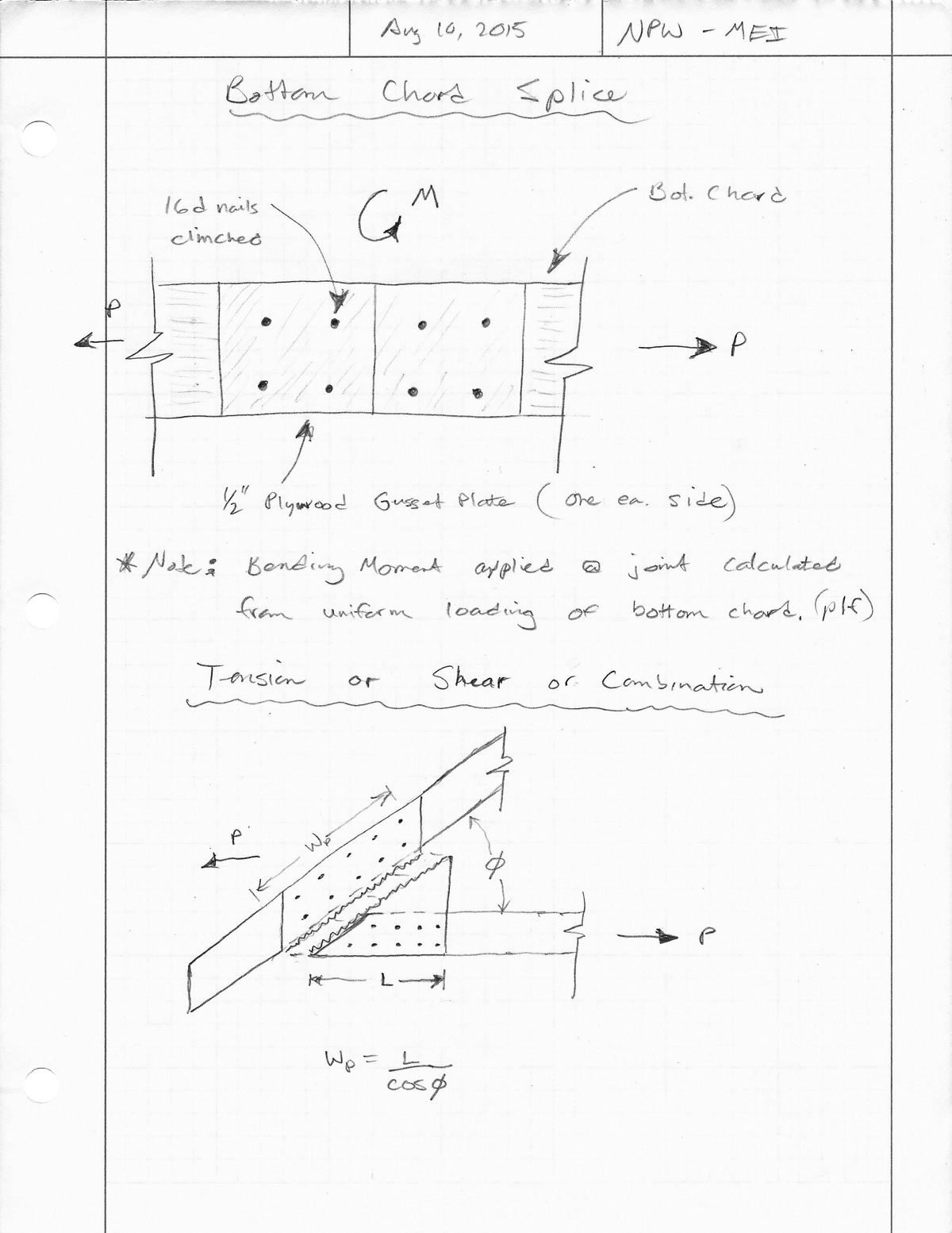
As a given I will probably spec. out a glue (ie. LNP-902) which I will not consider in the strength calculations to give an additional level of redundancy and margin to the design.

Looking through a number of documents I've seen clinched 3" nails, and unclinched 6d, 8d and 10d nails used. I've even seen some mention of Simpson SDS screws as well as drywall screws. Most of these documents are 50 years old or older so not a lot of recent data on this topic or so it would seem.

I am curious if anyone has any recent experience with using plywood or osb gusset plates on wood trusses and what was their fastener of choice and why?

I really like the idea of 3" nails that are clinched (less nails = less labor) however would a smaller diameter nail be less prone to splitting the wood members even though there are more of them and they are spaced more closely together?

I'm also considering ringshank nails since the cyclic loading on a truss might have a tendency to back the nails out over time, however the shear strength of these nails is a question needing further investigation.

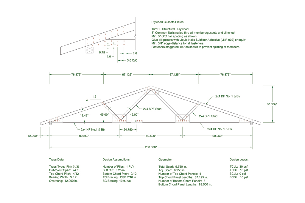
For the actual gusset plate material I'm considering 1/2" DF Structural I Plywood, however I would also like to have 3/4" PLY, 19/32" PLY and 7/16" OSB as additional options. I've actually see 7/16" OSB used in a lot of home built trusses and I'm actually guilty myself of my own home brewed trusses for a small storage shed using drywall screws and 7/16" OSB (8 ft. span). Other than the strength design values are there any other caveats to using OSB in this application?


A confused student is a good student.
Nathaniel P. Wilkerson, PE
 
Replies continue below

Recommended for you

I'm no structural guy, but OSB gussets would scare the he!! out of me. I can understand for a garden shed, but for anything else, . . . .

It is better to have enough ideas for some of them to be wrong, than to be always right by having no ideas at all.
 
I personally wouldn't design a new truss with plywood gussets. Occasionally, we run across these in existing conditions where we have to defend them. But for new, why not just have pre-manufactured trusses? I gotta believe they would be cheaper. If it's a small area where pre-manufacturered trusses wouldn't make since, how about just using a ridge beam? I'm no framer, but it seems like these would be a pain to install and QC to make sure all nails are installed properly.
 
As I mentioned above I created some small 8' trusses for a small shed. In retrospect it would have been just as easy to use a ridge beam and rafter it out. I would not typically create my own trusses either, too easy to just order some from a truss plant. However, there are situations where site built trusses make sense, mostly remote locations where the delivery charges are too high and just don't make sense. Also a lot of farmers and DIYers like to make their own for Cat I structures.

A confused student is a good student.
Nathaniel P. Wilkerson, PE
 
This is a bit out of my area, but as an aircraft repairman working on wooden structures, I would suggest that if you are using glue to take some of the shear loads in the gusset, that you make sure the glue joints are clean. I have been on construction sites where plywood gussets glued and nailed have been used, and I was not impressed with the attention given to the glue joint surfaces.
B.E.

You are judged not by what you know, but by what you can do.
 
I have used these as in field repairs. I never use screws, less ductile, especially not drywall screws. I don't like OSB but you can get the numbers to work out. I typically like to use longer 3" or 3.5" nails and crimp them. the crimp action stops them from backing out and allows the nail to be used in double shear as opposed to single shear action. Gusset both sides, always.

The few spreadsheets i made (not nearly as nice as yours!) i have used double shear nails, glue to keep wood from splitting, 15/32 & 19/32 structural rated sheathing and specify the strength axis or design based only on the weak direction (conservative)

Few things to consider is the geometry capacity of the gusset in tension/compression, and geometrically how many nails you can get into it. I usually make sure that my plywood can handle 100% of the load transfer at about 66% of my nails. Since each nail transfers 100#, i want my gusset to handle 133# from each nail (numbers are made up). Geometrically this is really only an issue in tight corners like Top-Btm Chord connections.
 
Thank-you EngineeringEric for some valuable insight. I apologize for my delayed response.

I really like the idea of clinched nails and I think that is the direction I will go. Determining the number of nails to use seems pretty straightforward however I'm a little bit conflicted right now as to how best consider the tension and shear strength of the plywood. In some cases the joint line of the plywood is not perpendicular or parallel to the applied load. In these cases would it be appropriate to use the Hankinson Formula (NDS 2012, Appendix J) combining the shear strength and tensile capacity of the plywood?

A confused student is a good student.
Nathaniel P. Wilkerson, PE
 
I'm just finishing up a barn with 28' gambrel trusses. To answer one commenters point about manufactured trusses, these trusses were to big to transport intact (about 30 wide, and about 16' high), so they still would have had to be assembled locally from half scissor trusses. The result would have been less usable second floor space. The original design is for locally fabricated trusses using 1/2 plywood gussets with 8d nails set 2" on center. The first side, I set the nails on a slight angle so it didn't penetrate the back side of the 2X truss material. The plans called for construction adhesive on the gusset/truss interface. The basic plans came from here but I modified the structure to use 2X6 walls and prefab trusses for the second story floor allowing a clear span for the first floor. Overall it came out well. Overall dimensions of my building are 28'X32" with a full second floor.

It took about 4 days to cut all the pieces, and 3 or 4 days to assemble all 17 trusses. Make sure you have a nail gun, trying to hammer all those nails will kill you! My gun quit about half way through, and I had to wait a couple days for a rebuild kit to get it up and running again.
 
@dgapilot Did your local building dept. require additional engineering on the trusses?

I'm curious as to the grade spec'ed out for the plywood gussets.

With a 2-1/2" 8d nail you would theoretically penetrate through one gusset plate and then also through the 2x truss member with about 1/2" sticking out the backside. I'm assuming you had a gusset plate each side though so if you nailed it with both gussets plates in place you should be able to nail the nails pretty much straight.

Did they provide you with a nailing template or pattern or any specific guidelines regarding edge spacing and end spacing?


A confused student is a good student.
Nathaniel P. Wilkerson, PE
 
Local building department accepted what was on the plans. The plans were not certified by a PE, but were well done. Actually all I really used were the truss and dormer drawings from the plans kit I got, the rest I drew up on CAD myself. This is in MD where they are usually pretty tough, but I think that's more to collect $ for permits than to actually enforce the building code.

I'll have to look if they specified anything other than 1/2 CDX for the plywood. I don't think so. With the first side, I drove the nails on a slight angle so the end wouldn't stick all the way through. The 8D collated nails are only 2 3/8, not 2 1/2 so with a 2X @ 1 5/8 and a 1/2 plywood gusset, that's only about 1/4" long, easy to fix that with a slight angle.

There was no nailing template per say, just a note for 2" on center with 1" edge distance. On the 2X6s I set then in a square pattern, and on the 2X4s I did a diamond pattern. My nail patterns weren't what you would call precision, just what looked about right as I hammered away with the nail gun. The inspector didn't even really look at the nail spacing when he did the rough inspection.

The floor trusses they were more particular about. The company that built them provided drawings with a PE stamp.
 
I'm still working on the algorithm for the design of the gusset plates. My process so far goes something like this:

1.) Consider all load cases.
2.) Calculate worst case loads for each member
3.) Design members per TPI 1-2007 or 1-2014 (this part is already well defined within the truss calculator).
4.) Choose a nail size, then determine its capacity (per nail) depending on gusset material, gusset thickness and member material and single or double shear. Load duration factor comes into play here.
5.) Given the lateral loads on the fasteners via the truss members determine the number of fasteners into each member at each gusset plate/member interface.
6.) Determine a min. spacing, edge and end distance for the fastener size.
7.) Based on step 6 and step 5, and with the width of the truss member (top chord, bottom chord, web) determine the number of fastener rows possible and the required length of the gusset plate along the member to accommodate the number of fasteners. This will determine the min. size of the gusset plate based on fastener lateral capacity.
8.) Given the size of the gusset plate determined in step 7 check the tensile/shear strength of the gusset plate material. If capacity is too low increase size of gusset plate.

One item that is also undetermined at the moment is how to best deal with chord splices, especially bottom chord splices that are in tension and bending.

A confused student is a good student.
Nathaniel P. Wilkerson, PE
 
Chord splices i have done two things:

1) combine all fasteners and calculate the combined effect (Ix, Iy) and then apply the moment to group and axial and shear. The resultant is then used to find the governing fastener. Easy for spreadsheet that calculates force per nail. This is accurate but tricky to code... ive only done it by hand. I have wished to turn it into excel and possibly treat it by user entered number of rows. Ie 2 rows of 2 per row gives X capcity = NG. User increases to 7 rows of two fasteners per row.... Or a For/While loop?

2) the outer nails on each end of the chord splice handle moment, the middle ones handle axial and shear. So each side of splice gets 7 rows of 2 nails. row 1 and 7 create force couple to transfer moment (spaced 6*2"=12") and the middle 10 nails handle axial....


Your question on when the force is not aligned with a major/minor axis, I think the value for intermediate angles is basked on Hankinson-Formula... i may be thinking of something else so don't trust me :)

 
@EngineeringEric

I've actually done this sort of thing with a spreadsheet for a similar situation with portal frames and the moment capacity of the fasteners so I guess I had the answer all along but didn't even realize it.

See this thread:


The next big question is how to check the tensile capacity of the bottom chord splice (with moment applied) in regards to the strength of the plywood gusset plates. Section 8.7 from the TPI 1-2007 has an equation for dealing with this exact situation for steel plates I am wondering if it can be modified and adopted for wood gusset plates, the basic principles should be the same.


A confused student is a good student.
Nathaniel P. Wilkerson, PE
 
@dgapilot

Very cool, thank-you for sharing that. I imagine those would have been quite fun to assemble. I'm assuming you probably built some sort of jig so that they all came out the same size and shape with all of those angles and lengths.

My guess is you've enclosed them in gypsum so they are not available for inspection but I wonder how the fasteners and glue are holding up long term and if there has been any significant creep.

A confused student is a good student.
Nathaniel P. Wilkerson, PE
 
Made a jig on the second story floor. Except the muscle power to move them and flipping them over, it was pretty easy. Assemble them and put gussets on one side and stack them up. Flip, then install gussets on second side, then stand them up and stack at one end of the building. When they are all done, space them out, put temporary bracing and start sheathing. It was a lot of fun, I learned a lot. I'm still working on the siding and finishing up stuff. At 62, I don't think I want to build another building. Next one I'll pay someone else.
 
 http://files.engineering.com/getfile.aspx?folder=d4d59ac2-8878-48ec-9939-d02be5e77fbc&file=IMG_0651.JPG
What a rather nice analysis on a nail group. I like it :)

I will say that the chord splices i have done have always been out of nominal wood, not plywood. So you will have the same moment+shear+axial worry in the chord splices.

As for the calculation of them, i would lean towards a unity of the forces/capacity < 1.0.... However, it starts to get important with the number of plys and such when doing tension/shear/bending about the laminated layers. I usually design the panel points as M=0 for this reason. if my members can transfer all the force as a pin then i only have to worry about the axial and shear capacity. And that there is a table for in the NDS or one of the supplements.
 
Medeek, what is this "truss calculator" you refer to?
I work in the modular housing industry and our roofs are usually a combination of pre-engineered wood trusses (mitek, etc.), factory built rafter systems and plain old simple framing with a ridge beam. We use gusset plates all of the time. OSB and plywood. The rafter systems are similar to designed trusses, but since the roofs have to be hinged down for transport, we require gusset plates at the heels after the roof is extended on site, then install a knee wall and/or collar ties. (The truss manufacturers have a special steel hinge they use that negates the requirement for gussets). My biggest issue is not the design of the gusset itself, but getting to correct design loads. After that it is pretty straightforward to design the gusset. In my experience the fasteners control the design almost all of the time.

Beyond that, a thought about nails sizes.....although still used, hand hammered nails of the 16d, 10d, etc. variety of nails have been replaced with pneumatic nail guns. The are a myriad of options for these guns....and are usually specified by diameter and length, e.g. 0.131 X 3" nail. That is actually a longer 8d nail. As I said, you can get almost any combination of diameter vs length. Check your local lowes or Home Depot, or check out Senco and bostitch nails on their websites.

Again I am very interested in this truss calculator you speak of. I would really like to find a simpler, more streamlined calc as opposed to RISA, STAAD, etc.

You had mentioned you wanted to use the clinching technique to save money....not sure how having to,go back to each nail and clinch the tail is time efficient. Especially with the relative low cost of materials (nails) vs labor.

 
Status
Not open for further replies.
Back
Top