Eng-Tips is the largest engineering community on the Internet

Intelligent Work Forums for Engineering Professionals

  • Congratulations waross on being selected by the Tek-Tips community for having the most helpful posts in the forums last week. Way to Go!

Tub Girder Bridge Cracks_Trying to Figure Out What Caused Them 6

Status
Not open for further replies.
Replies continue below

Recommended for you

The edge distance may be a function of the drawing detail... as far as the welding what the the procedure for welding... any preheat? Any metallurgical testing of materials being welded? Any samples of the failures sent out for testing?

-----*****-----
So strange to see the singularity approaching while the entire planet is rapidly turning into a hellscape. -John Coates

-Dik
 
@ Enjoy learning_not working
i got the textbook, but due to FORM "regulations" i can't post them here for sharing, you could email me, and I'll send it to you
 
Full disclosure: I haven't designed a box beam since the late 20th C. Anyway, two things jumped out at me:
1) The wrap around weld. A friend who's been on the fabrication end for 30+ years once told me, never weld all around because the corners always lead to problems.
2) The angles in the cross frames just seem like they're undersized. Were the X-frames field welded? Sometimes, field welding is problematic. Aside from that, in Photo 14 I wonder if it's a material defect. I suggest checking the capacity of the member and the connection.
3) In Photo 5, the stiffener should have been welded full width.

The attached NSBA Guide to steel boxes be of help. I all post the NSBA fatigue guide.


 https://files.engineering.com/getfile.aspx?folder=136be711-a635-4449-964d-f5e48141b0e6&file=b955_sbdh_appendix4.pdf
External Diaphragm - The diaphragm should be connected to the top and bottom flange of the girder; current detail is not great and prone to fatigue. This crack could be a case of distortion induced fatigue (see section 2.4 of the reference posted by bridgebuster). As noted by bridgebuster, wrapping the welds around the corner probably isn't ideal either, but with a full depth stiffener style connection that wouldn't be an issue. Photo 3 shows what might have been a poor quality weld to begin with.

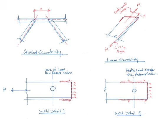
Internal Bracing - The weld between the diagonal bracing and the horizontal brace appears to be all closer to the end of the diagonal than the bolt. In terms of load transfer, 100% of the load is going through the reduced cross section of the angle. The net effective area here is going to be relatively small. None of the pictures show the weld of the heel of the angle (the third welded side), but based on where and how the angle fractured it doesn't look like it is a very long weld. That connection looks like there is significant eccentricity. I typically see this connection done with a large gusset plate which gives you lots of room to weld the angles and align the work points to eliminate eccentricity.

Stiffener to Top Flange Weld - bridgebuster, I respectfully disagree with your assessment that those stiffeners should be welded full width. That is a less favorable weld detail in terms of fatigue performance. There is typically a hold back of about 1/4", but that looks to be more like 1/2". So there should be more weld length, but not full width. The stiffener could have been wider as well to get more weld.

I suggest getting this bridge design reviewed. Based on what I'm seeing with some of the details (connection eccentricity, partial depth diaphragms, etc...) I suspect there might be some design issues that can't be resolved with maintenance. The bridge could use a coat of primer on the inside too. As noted in the report, some of the damage has progressed recently so this should be treated rather urgently. The description of the pictures indicate a continuous structure, so you might have tension in the top flanges of the girders where there are cracks in the stiffener welds....not great and will need to be repaired carefully.


CANPRO - You're correct. I should have included the weld tolerance. On NYSDOT projects there is 1/4" tolerance for stiffeners and connection plate welds. Thanks for pointing out my oversight.

regards.
 
Bridge & CANPRO

- Yes, seems like the wrap around weld is a problem and also the weld quality seems shady. The bridge was built around 1995. I have read from references and AASTHO guidance also that to reduced fatigue problems, contractors are required to remove the external diaphragms which was not done in the prior years (this bridge at least).

- The vertical stiffener weld connection as pointed out does need to be fully welded with a 1/4" cutoff at the end; seems like the weld has insufficient capacity.

CANPRO - Regarding the Internal Bracing diagonal cracks and fracture, I did not fully understand what you were trying to convey. Could you please explain it a little more. And, yes, the third leg of the weld is indeed longer and could be a source of eccentricity like you mentioned. Also, the current details that I have seen in recent projects does have gusset plates to connect these angles but seems like the existing detail was the norm back in the day.

Thanks for everyone who is contributing to this thread and trying to help out.

 
@ Enjoy learning_not working,

The attached file on box girders is from the old US Steel High Structures Design Handbook - forgot I had this - it goes back to 1978. It may offer some insight into the problems. I noticed the x-frames don't have gusset plate, which is different from what we would do today.

The AASHTO standard specs from the time required internal diaphragms or X- frames but waived the requirement for diaphragms/X-frames between adjacent boxes if they were designed according to the specifications.

 
 https://files.engineering.com/getfile.aspx?folder=1a5e5ea8-a0bf-46cb-8c43-a11264f9411e&file=USS_Box_Girders.pdf
ELNW: Your comment about weld length and eccentricity is correct, you likely have some local eccentricity in the connection. There also appears to be quite a bit of global eccentricity. See sketch below.

I've tried to clarify my comment with the load transfer through the bolt with a sketch. It appears that in your case, 100% of the brace load passes through the reduced section of the angle. If there were more weld length that extended beyond the bolt, you'd have less load going through the reduced section.

etips_ant436.jpg
 
Status
Not open for further replies.
Back
Top