Deker said:
When relying on rollover, do EORs typically specify whether the joist seat will be stiffened or unstiffened? I imagine that would impact the decision on whether it can be considered ductile.
I don't specify it but, at the same time, I have every expectation that it will either work unstiffened or we'll be doing something else (lugs etc). The cost differential between stiffened and unstiffened joist seats can be shocking in my experience. This is third hand information at this point but a very knowledgeable person here suggested to me once that the cost is less about the addition of the stiffeners themselves and more about messing up the ability to nest joists together for efficient shipping.
Deker said:
Granted, it's probably a moot point for this particular condition given that the amplified diaphragm demand is trivial compared to the shear transfer capacity of a tube collector with nominal welding.
Much depends on the situation. OP's situation is CMU shear walls by the sound of it. In my neck of the woods, that would mean that the tube lugs would get welded to small embeds in the CMU which would then become the brittle link in the chain and affect this calculus:
1) If I can make a go of it with joist rollover, I need to do that to stay competitive.
2) If I can make a go of it with a tube lug every other joist space, I need to do that to stay competitive.
Deker said:
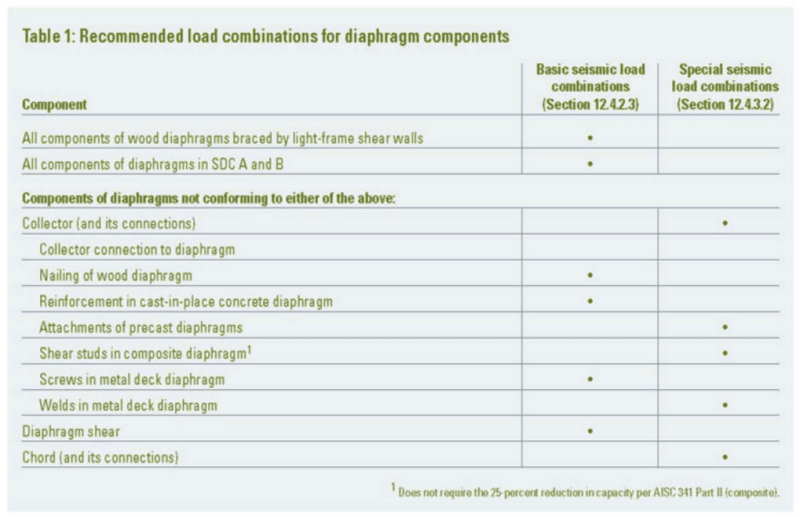
For those that subscribe to the unamplified demand / distributed strength argument, do you also disagree with the article I posted above that shear studs in a composite deck should designed for overstrength when delivering diaphragm shear to collectors?
I wouldn't say that I disagree with it, per se but, rather, that it's a bit of a surprise to me and it moves the conservatism needle a bit further over than I usually put it. Some thoughts:
3) I noticed that concrete to concrete shear friction is in the ductile category. That surprised me a bit. I've no doubt that grinding the interface down to a fine powder and then picking up some truss action probably does give you a decent hysteris loop, at least for a few cycles. But then, in a way , it still kind of is a version of unreinforced concrete shear.
4) In many ways, I see well distributed composite studs as being just another version of shear friction, albeit a lesser version between dissimilar materials. Moreover, the very procedure that we use to calculate the flexural strength of composite beams assumes some ductility in the connections between the studs and the slabs. So, in these respects, yes, I was surprised to see composite studs on the list.
5) In many ways, I see well distributed composite studs as being just another version of shear friction, albeit a lesser version between dissimilar materials. Moreover, the very procedure that we use to calculate the flexural strength of composite beams assumes some ductility in the connections between the studs and the slabs. So, in these respects, yes, I was surprised to see composite studs on the list.
6) Obviously my general argument about distributed connections would apply to this as well.
7) The article mentioned that the authors and some of their external associates were using this, more conservative approach despite it not really being codified. I have mixed feeling about that:
a) One the one hand, I celebrate a group going above and beyond what is codified based on their judgment. The rare, "race to the top" as it were.
b) I feel that it harms are profession a bit when you get stuff like this floating around that suggests that what many engineers are doing is incorrect / less correct without that stuff having made it into codes and/or widely accepted design guides yet. In sending out mixed messages to the design and construction community, we undermine ourselves I feel. Collectively, we seem wishy washy in a way that diminishes confidence in what we do. If it were up to me, we'd keep this kind of stuff close to our chests until a consensus is reached and disseminated. That said, I doubt that many contractors are reading Sabelli articles or identifying there reasons for relatively slight differences in connection strategies on EOR drawings.