Continue to Site

Eng-Tips is the largest engineering community on the Internet

Intelligent Work Forums for Engineering Professionals

  • Congratulations KootK on being selected by the Eng-Tips community for having the most helpful posts in the forums last week. Way to Go!

Twin beam- connected with UC offcuts. Effective length of LTB=1m? 1

Status
Not open for further replies.

Luke2020

Civil/Environmental
Jun 4, 2020
11
Hi all-

I have a twin beam scenario supporting blockwork and brickwork above.

A typical detail is to connect these twin beams with UC offcuts, welded to one beam and bolted to the other.

If these are spacaed at say 1m cc. does that reduce the effective length to 1m?

or will they assit with load share

or both?

I have had a user friendly document in the past covering this but i cant find it again.

discssion will be appreciated

 
Replies continue below

Recommended for you

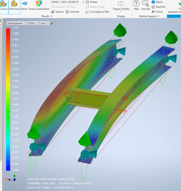
Here is one side with a perfect pin.

pinned_one_side_rwmend.png


We now get 50.9kNm. We have reduced the effective length from 6m to 4.4m!
 
human909 said:
The two bolt connection (not a single bolt) is pretty stiff for what is needed. Its a long way from a moment connection but it is also a long way from a pivot.

I assume you are talking about two bolts at one end, not one bolt on each end, which was my thought and drawn on my response to KootK above. The brace effect might be there when the flange of the brace against the web of the beam, this is not desirable though. But now I can see why KootK says the added end plate helps, if it is welded to the brace, then the brace itself is quite stiff, because geometry deformation is not likely to be significant for such short member length.

On the other thread, the connection in concern was tying floor beam to girder, thus it is reasonable to think the connections had at least two bolts on each end, and the floor beam is at lease 1/3 to 1/2 of the girder depth, therefore it can be seen as a sturdy braced point. In addition, by eye ball the floor layout, the floor beams were quite closely spaced, thus, the girder is considered fully braced by judgement call.
 
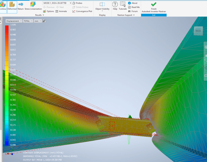
And at first you think that two perfect pins would give ZERO restraint to buckling. This would be true if the pin was perfectly central to the web of the beam. However any normal attachment would likely have some horizontal eccentricity to the web centre. This restrains the beams slightly as in the lowest buckling modes the distance between these points change. With two pinned connections this cannot happen so the buckling occurs at moderately higher loads.

2_pins_ivxoka.png

39.8kNm (5.2m effective length reduced from 6m)

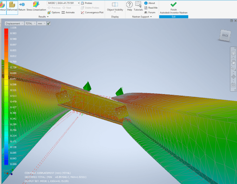
2_pins_greater_eccentricity_a4rruh.png

41.75kNm (5.05 effective length)
Just gained from moving from 30mm eccentricity to 50mm eccentricity.

** Disclaimer. These buckling moments are not the capacity of the members. This value is used to calculate your slenderness reduction factor for your beam.
 
retired13 said:
I assume you are talking about two bolts at one end, not one bolt on each end, which was my thought and drawn on my response to KootK above.
Yes. This is what is drawn and specified. Though I can understand the mistake.

retired13 said:
The brace effect might be there when the flange of the brace against the web of the beam, this is not desirable though.
Yes this is exactly what is occuring. The stub prevents twisting of the web. This provides significant restraint against LTB. I don't see why it isn't desirable.

retired13 said:
then the brace itself is quite stiff, because geometry deformation is not likely to be significant for such short member length.
Even for longer lengths the brace is extremely stiff for what is needed. The stubs we are looking at here are far stiffer than needed.

retired13 said:
On the other thread, the connection in concern was tying floor beam to girder, thus it is reasonable to think the connections had at least two bolts on each end, and the floor beam is at lease 1/3 to 1/2 of the girder depth, therefore it can be seen as a sturdy braced point. In addition, by eye ball the floor layout, the floor beams were quite closely spaced, thus, the girder is considered fully braced by judgement call.
The distinction I was making in the other thread was LATERAL bracing. Those floor beams (without deck) don't provide lateral bracing. They do provide torsional bracing. There is a difference. Though as I've demonstrated to myself the torsional bracing provided by a typical floor beam setup is quite significant. At a preliminary guess effective length of 2x beam spacing would be pretty conservative. Though I haven't examined this thoroughly.
 
human909 said:
We now get 50.9kNm. We have reduced the effective length from 6m to 4.4m!

Don't sound the alarm. Also 1.04626mm max. deflection? Can you provide beam size and length?
 
human909 said:
The distinction I was making in the other thread was LATERAL bracing. Those floor beams (without deck) don't provide lateral bracing. They do provide torsional bracing.

Note, Yuri and AISC requires one of the two types of restraint, torsion or translation, to be considered effective. Yes, the OP didn't mention flooring, but just by engineering judgement, what is that support system is likely for?
 
retired13 said:
Don't sound the alarm. Also 1.04626mm max. deflection? Can you provide beam size and length?
This is linear (eigenvalue) buckling analysis. I'm only putting a nominal 1kNm on each end and then running the model to reach the buckling modes. The displacement is meaningless. (I could probably do a non linear buckling analysis with the result of the linear analysis but this is a fair bit of work.)

retired13 said:
Note, Yuri and AISC requires one of the two types of restraint, torsion or translation, to be considered effective.
Well yeah. That was my point. The joints don't provide transnational bracing. I've now stated many times that they do offer some torsional restraint. However like I have said torsional bracing if it isn't stiff enough isn't going to reduce the effective length to the joist spacing. I have seen little good guidance on the effect of torsional stiffness of members and connections and it's effect in reducing the effective length. My local code seems to ignore it completely (AS4100). This is where more complex buckling analysis comes in. The effective length concept is really just a simplifying shortcut.

retired13 said:
Yes, the OP didn't mention flooring, but just by engineering judgement, what is that support system is likely for?
Not all flooring can be relied upon as an effective diaphragm. Again this was discussed at the end of the previous thread.


EDIT
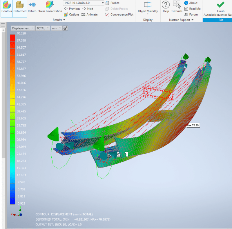
OK I ran the non linear analysis of the same beam displayed earlier. (2 pins in restraint, buckled 41.75kN) I put 50kN into it in 5kN increments.
25kN: 23.5mm max deflection (0.94mm/kNm)
30kN: 28.3mm max deflection (0.94mm/kNm)
35kN: 33.1mm max deflection (0.94mm/kNm)
40kN: 38.4mm max deflection (0.96mm/kNm) twisting barely perceptible
45kN: 44.6mm max deflection (0.99mm/kNm) slight twisting
50kN: 70.3mm max deflection (1.41mm/kNm) significant buckling twist

As you can at 40kN and 45kN the max deflection has increased slightly indicating that it is starting to buckle. At 50kN the beam has well and truly buckled

non_linear_roqlfv.png

(Deflection NOT to scale)

Note this too 15mins just to process the analysis, most of that time was spent on convergence on the last increment. That is why non linear buckling analysis is alot of work!
 
Any metal decking has to be designed to prevent tearing, buckling, distortion, then combined with floor beams to form lateral load carrying system. Since the double bolt connection does have capacity to resist torsion, unless lateral deflection of the diaphragm is excessive, there are both types of bracing present in the system, thus the floor is stable.

I am not writing off the significance of computerized design/checking, but it can't out weigh the traditional method provided by the code. I would like to believe, the traditional method is quite stringent, that in general it will yield more conservative result in any event. Also, by hands on practicing code equations/formula, one gain familiarity of variables/parameters that affecting the beam strength. Once one stands on the firm ground of understanding, with good modeling skill, computerized analysis and design would be preferred for increased productivity.

I ran a series of evaluation on wide flange beams, using AISC 9th, Eq F1-8, with Fb = 0.6 Fy, and Cb = 1.0. Below were the results.
W18x50, Lb <= 132" (11'), Ma = 160 k-ft
W21x50, Lb <= 93" (7'-9"), Ma = 170 k-ft
W24x55, Lb <= 83" (6'-11"), Ma = 205 k-ft
 
Retired you seem to be jumping around between topics with little coherency. I'm getting the feeling you don't understand what has been discussed.

retired13 said:
Any metal decking has to be designed to prevent tearing, buckling, distortion, then combined with floor beams to form lateral load carrying system. Since the double bolt connection does have capacity to resist torsion, unless lateral deflection of the diaphragm is excessive, there are both types of bracing present in the system, thus the floor is stable.
I personally don't rely on grated floor mesh to function as a diaphragm floor. I can use light hand pressure on a guard rail to significantly twist a channel member supporting floor grating.

retired13 said:
I am not writing off the significance of computerized design/checking, but it can't out weigh the traditional method provided by the code.
The 'code' is limited and generally has allowances for more accurate buckling analysis. It also offers limited or even no guidance regarding determining effective lengths for torsional restraints in the absence of lateral restraint.

retired13 said:
I would like to believe, the traditional method is quite stringent, that in general it will yield more conservative result in any event.
Please explain the traditional method used to determine a critical buckling moment or the effective length when the restraint is only a torsional and not a lateral restrain on one of the flanges. I'm all ears if you have a simple process to do this.

retired13 said:
Also, by hands on practicing code equations/formula, one gain familiarity of variables/parameters that affecting the beam strength. Once one stands on the firm ground of understanding, with good modeling skill, computerized analysis and design would be preferred for increased productivity.
Huh!? You seem not to be understanding things here at all. Code equations drastically simplify very complex behavior. It doesn't help one gain familiarity. And regards to productivity? Code equations are significant faster than computerised buckling analysis. You don't choose a buckling analysis route for increased productivity!!

Oh and stemming from other discussions. Agent666 demonstrates very well of a circumstance where the 'code' falls well short and is potentially dangerously unconservative.
 
I have identified code provision in my response, you can check into it, and find historical development of that equation/formula. If you want to argue with the code, or go one step further, with Yuri, then please proceed, I couldn't explain/comment well with a few computer outputs without knowing any background details/parameters.

Lastly, what is the base of the computer program if it is not abide by the code and known theory. The end result of computer analysis, with all parameters holding constant, therefore should agree closely with the hand calculation specified by code. If not, you shall question its validity provided no mistakes in the hand calculation.
 
Interesting results human909, thanks for putting in the time & effort to generate them for us.
 
Kootk said:
Interesting results human909, thanks for putting in the time & effort to generate them for us.
You are welcome. It is alot of time and effort. I think the last time I was busy and got exhausted from it all. Running the non linear analysis was great for LTB but it really takes alot of computer run time. Convergence doesn't come quickly when your beam is buckling and twisting. (For columns you generally give up or the program fails as the buckling runs keeps running away.)

If you have any further questions about LTB topic then feel free to ask and I might find the time to explore it too. I can get the model behaving very well that yields consistent results compared to codified theory and other analysis tools such as Mastan and LTbeam. But it can offer more when you start adding real world restraints like torsion restrains between rows of beams.

What can't easily be done though is modelling of multi bolt cleat connections. These are stiff until the bolts friction slips and then they are loose until the rotational slop is take out in bolt hole tolerances. It probably is possible but that an adventure for another time.


retired13 said:
I have identified code provision in my response, you can check into it
You did not answer how the effective length is determined in the absence of lateral restraint. In all the codes I've seen you need to determine the critical/refernce buckling value via effective lengths or buckling analysis.

retired13 said:
The end result of computer analysis, with all parameters holding constant, therefore should agree closely with the hand calculation specified by code.
That is incorrect. Throughout out codes with have various simplifying shortcuts that make extremely complicated problems into more simpler problems. In most cases the code is going to be conservative, but not always. Furthermore most codes incorporate provisions for more advanced buckling analysis methods like I've been running.
 
Effective brace length Lb is determined by the equation I referred to (ASIC 9th, eq. F1-8) as shown below, or you can use Yuri's equation, which was AISC equation based upon.

Fb = 12000Cb/(Lb*d/Af) <= 0.6Fy, in which, 1.0 <= Cb <= 2.3, d = beam depth, Af = area of compression flange

Simplified short cut is in other aspects of analysis, when dealing with material strength and property, we have to follow exactly the code provide equations and parameters. Don't miss match the issues.
 
Human909. This is a considerable amount of effort and is very useful.

It's monday morning here in the UK, im going to have a cup of coffee and digest all of the above discussion.

A quick reply regarding the 2 bolt connection.

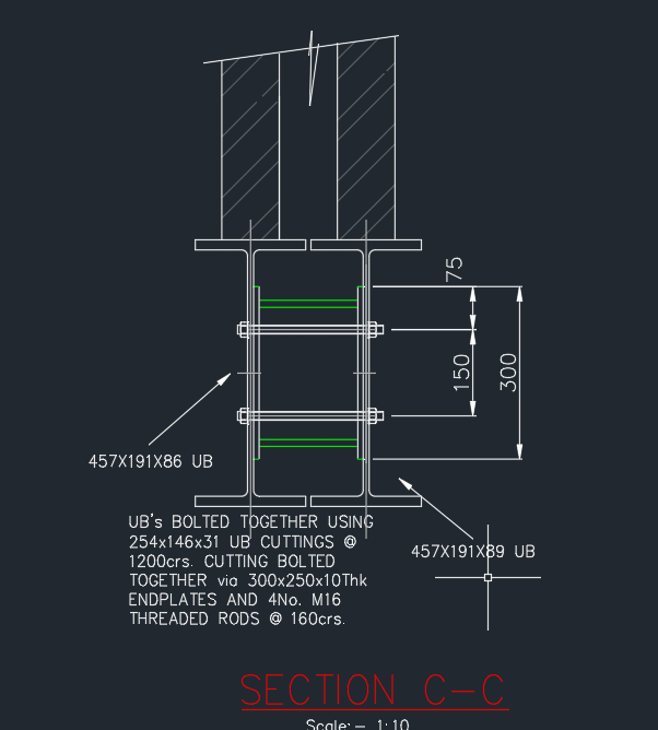
We sometimes use a more robust detail that would achieve a moment connection between the two as seen below. so seems like it could be best to specify this as standard.

twin_beams_1_rzxnmk.png
 
My first reaction to that is I don't like the use of such long bolts/threaded rod. I don't see it being a problem for this use. But I wouldn't describe it as a full 'moment connection'.

But either way both that connection and the previous one I would suggest are more than sufficient for LTB restrain purposes. For load sharing that is another interesting issue but I would tend towards caution until well demonstrated otherwise. Oh and like was mentioned earlier don't forget to consider twin beam LTB. When your beams are that close together and well restrained with each other then the twin beam case becomes dominant for longer spans. KootK linked the relevant equations, it was discussed in more detail elsewhere.

Enjoy your coffee. I probably won't be contributing for a day or so.
 
Status
Not open for further replies.

Part and Inventory Search

Sponsor