Continue to Site

Eng-Tips is the largest engineering community on the Internet

Intelligent Work Forums for Engineering Professionals

  • Congratulations MintJulep on being selected by the Eng-Tips community for having the most helpful posts in the forums last week. Way to Go!

Two harmonics questions

Status
Not open for further replies.

veritas

Electrical
Oct 30, 2003
467
For the harmonics gurus,

I have read in quite a few texts on power system harmonics that a VFD is a non-linear load and so is a source of harmonics. Thinking about it I would say that this is misnomer (the way I see it anyway). The VFD is not a source or sink of electrical power. Considering a 6-pulse VFD, the current drawn by the VFD from the line is two pulses every halfwave so 4 pulses per cycle. Yes, they are not sinusoidal and can be represented as the sum of the fundamental and 5, 7, 11, 13, 17, 19, etc harmonics. These are positive phase sequence harmonics that are supplied from the source to the VFD load.

This I have verified using PTW. For a single load on the system the I_THD% at the cable supplying the VFD is nearly the same as the I_THD% at the utility point way upstream (all other loads, capbanks, etc. out of service). When the other load is put into service, the I_THD% at the source decreases dramatically. The reason is that it still supplies the harmonic current as before, but to this is added load of all the DOL drives, other VFD's, lights and power, etc. So the fundamental increases but the harmonics not as much.

Am I on the right track so far?

The real conundrum for me is the effect of a pf correction capbank on harmonics. For example, without the bank, the cable supplying the MCC has I_THD% = 42%. Once the bank is in service I get I_THD% = 18.7% for that same cable. Why? I've also noticed that the capbank has a series inductor and so it is a tuned filter to the 3.77 harmonic. This makes a huge difference. When I model the capbank without the inductor the I_THD% in the supply cable shoots up to 155% as there is 5th harmonic resonance.

I'm trying to get my head around why the capbank has such an influence on the harmonics. It draws leading fundamental current from the source. And then...

Thanks.
 
Replies continue below

Recommended for you

The impedance of the capacitors goes down as the frequency goes up.
The impedance of the inductor goes up as the frequency goes up.


Bill
--------------------
"Why not the best?"
Jimmy Carter
 
Yes, that I do know but how does that relate to capbanks and harmonic currents due to 6-pulse VFD's?
 
Try modeling the cap bank/inductor combination at the harmonic frequencies.

Bill
--------------------
"Why not the best?"
Jimmy Carter
 
The capacitor and inductor in series (single-tuned harmonic filter) has a different impedance at different frequencies. At the 5th harmonic (300 Hz on a 60 Hz system), the impedance is low and a lot of the 5th harmonic current generated by VFD gets shunted through the capacitor. For mathematical analysis purposes, the VFD can be considered a constant current source for harmonic currents. The system source is a pure 60 Hz source and does not supply 5th harmonic current. Without the filter, all of the 5th harmonic current from the VFD flows into the system.

It is the modeling of the VFD as a constant current source that makes things work out. The VFD is not really a source, but is a non-linear load (impedance is different in different parts of the voltage cycle) that creates harmonic currents. Treating it as a constant current source at different harmonics makes the analysis easier by allowing you to analyze the system for each harmonic independently.
 
What you are referring to is called "Total Demand Distortion" and is actually what you are required to "control" within your facility. Current distortion is based on how much non-linear load you have compared to your TOTAL load, your DEMAND.


" We are all here on earth to help others; what on earth the others are here for I don't know." -- W. H. Auden
 
jghrist

I hear what you say and I fully grasp that analogy, it is synonomous to the belief that a capacitor bank supplies the vars to the local load. This is in reality a misnomer as the capbank is neither a source or sink of electrical energy. In reality the capbank draws leading current from the source which opposes the lagging reactive current drawn by the inductive load. The resultant reactive current is thus less.

I'm trying to grasp the interaction between the VFD and capbank in the same way. If the VFD is not truly a source of harmonics then one should be able to explain the effect the capbank has on the current distortion by considering the current drawn from the source by the capbank vs the current drawn from the source by the VFD. That is what my question is all about. It is about being able to properly conceptually grasp what really happens.
 
jraef

Yes, need to look into this one a bit deeper. Thanks for the pointer.
 
Is your cap bank at the motor, at the MCC, or upstream of the MCC?

What do you consider to be the source for reactive power if not a capacitor? Each power system cycle, energy flows from the electric field in the capacitor to the magnetic field in the motor and then back to the electric field in the capacitor. Upstream, the utility has capacitors in the form of both shunt capacitor banks and shunt impedance of transmission lines. All the way back at the generator, many utilities try to keep the generator running near unity power factor.


My capbank is attached at the same bus as the VFD.

backn4life - Capbank is not a source of electrical power in the greater scheme of things since over one complete cycle the nett influx of electrical energy to the capbank is 0 (neglecting small resistive losses). On a network scale, the capbank draws leading current from the source. On a capbank scale it means the capacitor gets charged and discharged cyclically at the frequency of excitation which is either 50Hz or 60Hz in power system applications. But the energy it discharges is not energy it generated itself! It received it externally from the network on the positive half cycle and discharges it on the -ve when the system volts goes below capbank volts.

Yes, you can think of it as discharging into the motor. But what if there was no motor? That energy is still discharged back into the system. I think it is more correct to think of it as the capbank drawing leading vars and the motor lagging vars and these oppose each other to reduce the overall var requirement from the source. They are in anti-phase so on an instantaneous power level, the energy discharged by the capacitor in one half cycle is the area under the half cycle curve. For that same half cycle the energy drawn by the motor is energy under its curve, but that curve is negative if the capbank curve is positive.

Hope that is as clear as mud!
 
In the greatest scheme of things, over one complete cycle of the universe, are there any sources of electricity [ponder]

From the utility's perspective, a customer connecting a cap bank as a source of reactive power is quite similar to a customer connecting a capacitor bank as a source of real power. Under steady state conditions, all the utility meter can see is the net real power and the net reactive power. If you turn off the motor, both a capacitor and a solar panel will push power onto the utility grid.

Let's think about a case of an unloaded motor and a capacitor bank sized to exactly match the no load reactive power draw of the motor. During steady state, there would be zero reactive power flow from the utility meter and only a small amount of real power flow to compensate for losses. The upstream utility system in this case provides reactive energy during the motor starting transient.

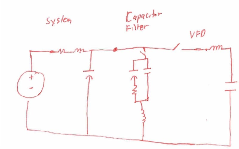
Does the schematic below adequately represent your system? As the VFD diodes cycle between conducting and blocking, they will impose transients on the system. Since the cap bank is experiencing transients, it will draw other than fundamental current. Depending upon the exact impedance values in the filtered capacitor bank, the bank can either exacerbate or mitigate harmonics.

VFD2_zi605z.jpg
 
Hmmm. Capacitor is drawing leading current and motor is drawing lagging current. The common reactive current cancels on the wires going to the utility.

Wouldn't that mean the current must be flowing between the capacitor and motor?

Since that current is reactive current, wouldn't that mean reactive power is flowing between the capacitor and motor?

You didn't add the capacitor bank to your plant power system first. You accomplish nothing useful by starting with an empty industrial building and connecting a capacitor bank to the unloaded power system.

You first install machines with motors in the plant. These motors can produce a real mechanical power output on their shaft which can then be used to do some form of useful work which then generate revenue for your plant.

Once you have the motors connected, you then find out that they are drawing reactive power from the utility and the utility is billing you for that reactive power. So, you add the capacitor bank to source the reactive power for the motors instead of having the utility source the reactive power and bill you for sourcing it.

Overall, you're confusing real power and reactive power. You have wrongly claimed the capacitor can't be a source of reactive power for the power system because the capacitor is incapable of sourcing real power.


Now, to your first question. There are 2 different things that can happen with a VFD and capacitor bank on the same power system.

#1 - the capacitor bank becomes the source for some of the harmonic current, which reduces the harmonic current drawn from the source.

#2 - the harmonic current flowing from the source to the VFD will cause harmonic voltage drops in the system. These small harmonic voltages can excite the resonance circuit that exists between the source and capacitor bank.

 
Shouldn't we be considering the rectifier in between the AC line input to the VFD and the capacitor bank on the DC bus?

Consider the simplest case of a passive diode-bridge rectifier. The rectifier will only pass current to the capacitor bank when the instantaneous voltage of the AC input exceeds the voltage of the bank. This generally only happens at the peak of the AC sinusoidal waveform.

I like to refer to this as the drive "gulping" current at these peaks. Of course, this yields a lot of higher harmonics in the current waveform.

Curt Wilson
Omron Delta Tau
 
From the utility's perspective, a customer connecting a cap bank as a source of reactive power is quite similar to a customer connecting a capacitor bank as a source of real power. Under steady state conditions, all the utility meter can see is the net real power and the net reactive power. If you turn off the motor, both a capacitor and a solar panel will push power onto the utility grid.

Mate, a capacitor is not a source of steady state power - real or reactive. It can only discharge stored electrical energy back into the system when system volts drop below capbank volts (if it has any). This is very different to a solar panel which is a generator in essence.

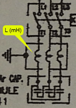
I'm a bit puzzled by your drawing above. Here is an extract from the actual drawings:

Cap_with_series_inductor_mvoncg.png


The cap has a series inductor as per the drawing above. Which is the cap with series inductor in your drawing?
 
You logic makes no sense. After installing the capacitor bank in your plant, the bank begins to supply the VARs for the motors instead of the utility supplying the VARs for the motors. The utility meter shows a reduction in the VARs and the motor VAR demand didn't get reduced so the VAR's the motors require are being sourced by the capacitor bank. Yet, somehow the capacitor isn't the source of the VARs the motor needs?

You are still wrongly claiming the capacitor can't be a source of reactive power because the capacitor is incapable of sourcing real power. reactive power does not equal real power. The capacitors can source the first one without being capable of sourcing the second one.


On another note, you don't do the traditional calculation of a capacitor to correct power factor when you need to correct the power factor of a VFD. You filter the VFD harmonics.
 
Assuming the inductive load is downstream of the PFCC on a simple radial system, the capacitors will reduce VAR demand to the point of the PFCC. The reactive energy will alternate and transfer between the inductive load downstream and upstream capacitors.

If you install a harmonic filter in parallel with the source, the filter provides additional parallel path to circulate harmonic currents between the VFD and the filter hence reducing the incoming harmonic distortion.

"Throughout space there is energy. Is this energy static or kinetic! If static our hopes are in vain; if kinetic ù and this we know it is, for certain ù then it is a mere question of time when men will succeed in attaching their machinery to the very wheelwork of nature". û Nikola Tesla
 
Although this statement describes a capacitor applied to a DC system, it incomplete for a capacitor bank applied to a 3 phase AC system. In an AC system, each individual capacitor can is either charging or discharging all1 the time. As reactive energy is discharging from one capacitor can, the other capacitor cans are charging. The total stored energy in all three cans is constant during steady state operation. What would you expect to read from a kvar/kvarh meter installed on a capacitor bank?
1Each half cycle, there is an instantaneous moment as the voltage crosses zero where the individual capacitor can neither charges nor discharges.​


There are several kinds of filtered cap banks; I assumed some additional RLC components to make a higher Q filter and it looks like your cap bank is a simple tuned LC circuit.

How about trying the thought experiment of treating the VFD as a constant current source in order to do a first order approximation? If so, this problem can be analyzed using the superposition theorem by do one analysis for the Thévenin60 hz source, and additional analysis for each harmonic produced by the Norton sources. Adding a capacitor bank dramatically changes the equivalent source impedance upstream of the VFD.


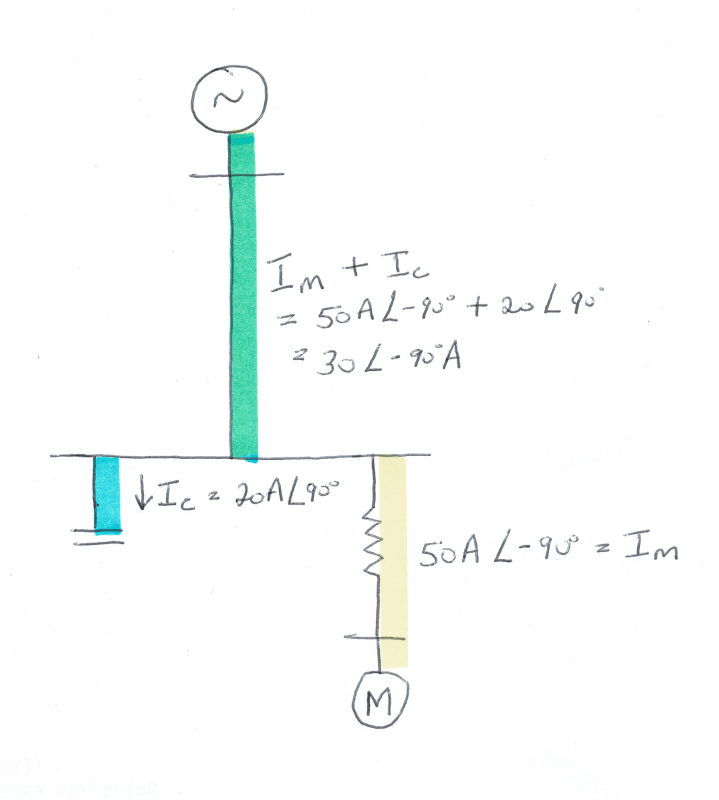
Maybe the following illustration will help:

Cap_and_motor_currents_qjhvhg.png


The yellow lagging current flows from the source to the motor regardless of whether there is a capacitor bank or not. The blue leading current flows from the source to the capbank regardless of whether there is a motor or not. The NETT effect is a reduction of reactive current (and thus reactive power) from 50A lagging to 30A lagging from source to MCC (blue + yelow = green). I am more comfortable with:

VTer said:
The reactive energy will alternate and transfer between the inductive load downstream and upstream capacitors.

But I am not comfortable with the capbank being a "source" of vars because by the same argument so is the motor if the reactive power alternates between the motor and capbank.

You are still wrongly claiming the capacitor can't be a source of reactive power because the capacitor is incapable of sourcing real power. reactive power does not equal real power.

Going through my previous post I could not find where I said reactive power equals real power. I said the capbank is not a source of steady state power - real OR reactive.

Getting back to the harmonics issue:

Lionel, I would still greatly appreciate it if you could provide more detailed labels on your drawings. I do believe I can learn from it but I need more clarity as to what the various components represent.

VTer said:
If you install a harmonic filter in parallel with the source, the filter provides additional parallel path to circulate harmonic currents between the VFD and the filter hence reducing the incoming harmonic distortion.

Are you saying that the capbank with the series inductor acts like a harmonic filter? Since the capbank is in essence a tuned filter to the 3.77th harmonic, does that mean then that it is effective only in reducing the 5th harmonic and not the others?

Thanks.
 
Sigh. your comments "the energy it discharges is not energy it generated itself" and "the nett influx of electrical energy to the capbank is 0" are both referring to real power, not reactive power.

Overall, your argument seems rather silly. Following your logic, the utility can't be a source of reactive power since the net reactive power flowing to or from the utility is also zero.

Generally speaking, a capacitor-less AC grid system would have an inductive-reactive problem, meaning the utility generation would have to source a lot of inductive-reactive current into the grid system. So, capacitors are added throughout the grid system to supply this inductive reactive current instead of the generation sourcing it. In other words, the capacitors become the new source. This is why utility or power system engineers view the capacitors as a source of VARs. You can claim it works differently, but good luck getting much traction with that.

 
I think that it may be time to blow the foam off of the beer.

Bill
--------------------
"Why not the best?"
Jimmy Carter
 
Status
Not open for further replies.

Part and Inventory Search

Sponsor