diegoaml95
New member
Hello I want to understand two things.
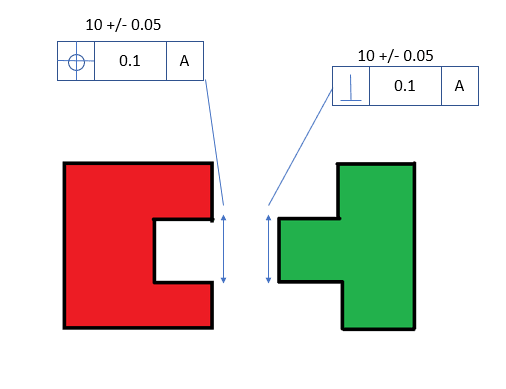
First, Im designing some parts and when I wanted to assemble them I took the worst case boundary as 0.3 considering the linear tolerance of 0.05 from both parts and then considering the tolerance of position and the perpendiculariry, but one Sr. engineer told me that the real interferance is 0.1 just considering the linear dimensions, why not considering the GD&T tolerances????
Second, I want to fully undestand how and why they make two or more datum reference frame besides ABC.
I want to become a master at this, I dont know why but I enjoy doing this, so if any one could tell me any advice or recommend any great book or courses that will be great!! I need a mentor!