Continue to Site

Eng-Tips is the largest engineering community on the Internet

Intelligent Work Forums for Engineering Professionals

  • Congratulations KootK on being selected by the Eng-Tips community for having the most helpful posts in the forums last week. Way to Go!

Two retaining walls on the common footing 1

Status
Not open for further replies.

n3jc

Civil/Environmental
Nov 7, 2016
187
Greetings, I have to design a RC retaining wall as shown in the attached image bellow.

Wall 1 is high (4 m above the footing) and wall 2 is shorter (aprox. 2 m above the footing).
I have 2 RC walls on common footing. I was wondering how the earth pressure acts on wall1/wall2?

On wall 1 acts active earth pressure but does this have an impact on the wall 2? Is wall 2 loaded with both earth pressures - from wall 1 and from thr earth pressure between wall 1 and wall 2? Earth pressures depend on displacement of the wall, but what to expect in this case? I dont think there will be passive earth pressure acting on wall 2 because of wall 1 unless wall 1 is really stiff and there wont be any displacement going on there.

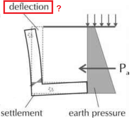
What is allowable displacement on the top of the wall (I havent find it in Eurocode 7 or American standards)?

Not my field, hope for some good advices.
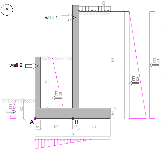
ozA_rspwze.png


deflection_j3gcyw.png
 
Replies continue below

Recommended for you


Active thrust developing on wall 1 will have limited impact ( depending on the size of b2) on the wall 2 . If the size b2 too narrow, the vertical soil load between two walls will not be linear ( gammasoil*h) due to silo effect. Drawing the failure surface for soil at b2 will help to see reduction at active load on wall 2.

I will suggest the design loading ;

- For wall 1; Active soil load for h3 ( Ea +Eq )- at rest resistance of soil for h4 at b2 (or conservatively active soil loading for h3)
- For wall 2: Active soil load for h4 ( Ea )
- For combined system ( for wall 1 and 2 ) overturning = active load for H ( Ea +Eq )
- For combined system ( for wall 1 and 2 )sliding = active load for H ( Ea +Eq ) - Passive Ep.


You will decide for the allowable displacement and wall tilt depending on the surrounding conditions. If only for aesthetics, you may use battered stem to compansate the tilt. If the concern is cracks etc at pavement , you may choose fatty sizes and choose at rest loading rather than active.


I agree HTURKAK.

Here are some secondary questions:

1) Where is the water table located?

2) Is wall 2 going to have planter boxes or an irrigation system behind it?

Aside from normal above grade weep holes in both walls; I'm thinking you will want some small holes in wall 1 below grade so that any water can move freely between the 2 backfill regions.
 
I'd like to add to what I have seen: there is a very real possibility (depending on the soil type) that the active earth pressure on wall #2 will be a partial pressure. (I.e. it will less than the full pressure due to the geometry of the soil behind it.)

A had a geotech give me some guidance on this some years ago (for a similar situation). The effect of the adjacent wall wasn't considered (as additive pressure to wall #2). Just the reduced pressure from the considerations I said above.
 
Some addition
Loading will also depend on backfilling stages. May be left backfilling will be delayed

To simplify the footing design one may study casting two seperate footings with some joint in between
Combined soil stress effect to be studied/geotech engineer can he consulted especially for F.E modeling and spring specifications.
 
I completely agree with HTURKAK.

As for his bullet point number 1, I believe he intended to say "passive" resistance and not "at-rest" resistance. For that one, I would not count on the passive earth resistance as reducing the forces in Wall 1. I would check it conservatively for the full active pressure (Ea + Eq).

The active earth pressures for the 2 different walls would certainly not be additive when checking global stability but should be checked independently when determining local force demands.

I am currently designing a very similar structure. One shared footing with 2 different wall stems of varying heights. The upper wall is the wingwall coming off a bridge abutment and the lower wall is for some planter beds. We went about it a different way and GRS wrapped the soil behind wall 1 and filled all but the top 2ft behind wall 2 with Geofoam.
 
Watch out drainage for wall 2, if water storage is not the scope.
 
This may be obvious, but here goes:

The soil pressure on wall 2 is at-rest, but there is no influence from wall 1.

Overall, the effect of the soil behind wall 2 is strictly weight. The lateral forces on wall 2 are equal and opposite on wall 1.

The pressure on wall 1 is is the net of the at-rest pressure from the front and the active pressure from the back.

Rod Smith, P.E., The artist formerly known as HotRod10
 
BridgeSmith said:
The soil pressure on wall 2 is at-rest, but there is no influence from wall 1.

Wall #2 may not be able to develop the normal active wedge if "b2" is not very large compared to the height of the wall, but how are the higher at-rest pressures developed onto it if wall #2 is not restrained from moving like a basement wall is?

The resulting forces on the walls can be a function of the relative stiffness between the two walls depending on how they are backfilled and compacted. The stiffness of the fill used in the b2 area could also influence the load sharing depending on the backfilling procedure and compaction.

I wouldn't make it that complicated and I would be conservative in the design, assuming whatever backfilling procedure provided will not be correctly followed.
 
I think BridgeSmith is essentially correct as far as theory goes (maybe with some modifications based on haynewp). However, this isn't a PhD thesis.... I would still do the DESIGN the way that HTURKAK suggested. It's reasonable and conservative.

Definitely put some consideration into drainage per Kootk.
 
Bridge Smith, I'm not seeing the at-rest earth pressure on wall 2. How do you come up with that?
 
Wall #2 may not be able to develop the normal active wedge if "b2" is not very large compared to the height of the wall, but how are the higher at-rest pressures developed onto it if wall #2 is not restrained from moving like a basement wall is?

Regardless of what the b2 dimension is, the soil between walls 1 & 2 cannot move (wall 2 is restrained, by the footing) hence at-rest pressure on both walls, assuming the backfill is compacted. If the backfill is dumped in loose, it might be closer to active pressure initially, but would eventually consolidate and exert at-rest pressure. Theoretically, if the difference in height of the 2 walls was great enough, wall 1 was flexible enough, and b2 was small enough, you could develop some passive pressure in the soil in front of wall 1, some of which would transfer through to wall 2, but I don't see that happening if the proportions of the wall are anywhere close to what's shown in the sketch.

The resulting forces on the walls can be a function of the relative stiffness between the two walls depending on how they are backfilled and compacted. The stiffness of the fill used in the b2 area could also influence the load sharing depending on the backfilling procedure and compaction.

In theory, perhaps, but for practical purposes, the stiffness of the walls is so much greater than the stiffness of the soil, that the influence of the backfilling order is within the (huge) margin of error of the soil pressure calculations. No need to try to be so exact when dealing with something so highly variable as calculated soil pressures.

Rod Smith, P.E., The artist formerly known as HotRod10
 
I think BridgeSmith is essentially correct as far as theory goes (maybe with some modifications based on haynewp). However, this isn't a PhD thesis.... I would still do the DESIGN the way that HTURKAK suggested. It's reasonable and conservative.

I like HTURKAK's approach as well, for the most part. For the reason's stated above, I would use at-rest pressure for design of wall 2. To be conservative, the OP could use active pressure for the resistance of the soil in front of wall 1, rather than at-rest.

I would also use h3, rather than H for overturning, but using H is conservative, so nothing wrong with that.

I agree with keeping it simple. I didn't mean to suggest a complicated or detailed design approach.

We rarely include passive resistance in front of a wall (Ep). Unless we are very confident that the soil will always be there, we would ignore it for the stability checks.

Rod Smith, P.E., The artist formerly known as HotRod10
 
BridgeSmith said:
Regardless of what the b2 dimension is, the soil between walls 1 & 2 cannot move (wall 2 is restrained, by the footing) hence at-rest pressure on both walls..

I still don't understand at-rest pressures developing on a wall that is not restrained at the top. The normal procedure is active for cantilever walls and at-rest for basement type walls. I have never seen where at-rest pressure was used in order to justify compaction amount behind a wall either.

BridgeSmith said:
In theory, perhaps, but for practical purposes, the stiffness of the walls is so much greater than the stiffness of the soil, that the influence of the backfilling order is within the (huge) margin of error of the soil pressure calculations. No need to try to be so exact when dealing with something so highly variable as calculated soil pressures

And I also stated that I wouldn't make it that complicated after I mentioned the interaction of the soil in the b2 area and relative stiffness of the walls.
 
I guess Bridgesmith meant that with limit back depth (of fill) and wall height, the deflection of wall 2 could be too small to allow active pressure to develop. A wedge analysis should be able to tell, but add works, why bother.
 
I still don't understand at-rest pressures developing on a wall that is not restrained at the top.

The active pressure condition requires movement of the wall after compaction of the soil, in order to activate the soil interlock, which allows some of the lateral thrust to be resisted internally. The top of the wall will deflect when the soil is compacted, but does not continue to move after it reaches equilibrium with the applied load.

Rod Smith, P.E., The artist formerly known as HotRod10
 
At-rest pressure is recommended by several sources for structural design of cantilever stems. It's more common in British/descended documents IME, eg CIRIA, Hong Kong. This is in case of compaction as BridgeSmith has said, or in case the FoS on sliding and bearing make the wall quite rigid. Active is however used for stability: no movement, no stability problem.

In this case, wall 2 can't get relief due to sliding or base rotation because the soil is contained above the base slab and moves with the wall. Only wall deflection contributes, unlike a typical cantilever wall.
 
I see. I’ve never seen it mentioned in a geotech report nor had such a situation come up. Thanks for the info.
 
Status
Not open for further replies.

Part and Inventory Search

Sponsor