Navigation
Install the app
How to install the app on iOS
Follow along with the video below to see how to install our site as a web app on your home screen.
Note: This feature may not be available in some browsers.
More options
Style variation
-
Congratulations TugboatEng on being selected by the Eng-Tips community for having the most helpful posts in the forums last week. Way to Go!
You are using an out of date browser. It may not display this or other websites correctly.
You should upgrade or use an alternative browser.
You should upgrade or use an alternative browser.
Type of joint ?? 3
- Thread starter Hudhaifa
- Start date
- Status
- Not open for further replies.
-
1
- #3
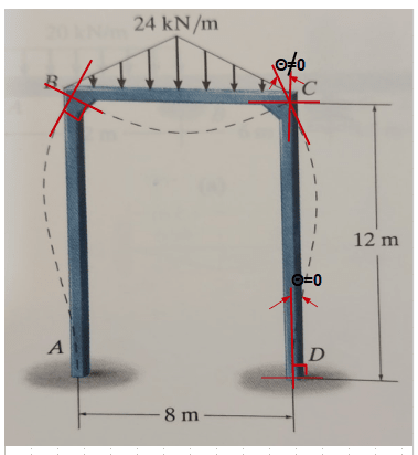
Nodes A and D are rigidly connected to something external to the frame. The rotation is zero at A and D.
Nodes B and C are not connected to anything outside the frame. The connection between AB and BC is rigid, meaning that the rotation at the top of AB equals the rotation at the left end of BC. (Similar with Node C.)
Nodes B and C are not connected to anything outside the frame. The connection between AB and BC is rigid, meaning that the rotation at the top of AB equals the rotation at the left end of BC. (Similar with Node C.)
JoshPlumSE
Structural
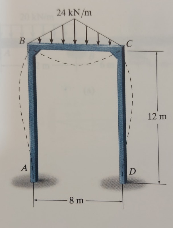
what is the type of joints B and C in the frame below?
This is a generic / conceptual drawing of a structure. The joints are drawn that way to demonstrate that it is a moment connection. It doesn't definitively say anything about whether it's rigid, or semi rigid moment connection. Though I would take it to SUGGEST that it's a rigid moment connection.
It definitely doesn't say anything about how the connection rigidity is achieved, whether it's welded or bolted or used end plates or what. Once you figure out what type of connection detail is used, then (and only then) can you definitively say whether it's rigid or semi-rigid.
-
1
- #5
Sorry about the last post - looked like a student question, but your posting history looks like you're not a student.
As drawn, the connections at B and C are rigid - the members will remain at 90 degree angles to one another. Why? Because that's what the author of the textbook wanted to call them. A fully rigid connection is a theoretical exercise. All connections will have some amount of deformation, but we break them down into pinned, semi-rigid/partial moment connection, and rigid/moment connection (or any of several other names depending on where you learned them). We assume a rigid connection has no internal rotation because the amount of internal rotation that does occur is minimal and can generally be neglected in practice.
Not sure what you mean by interpretation of the rotation at B and C.
A and D are external boundary conditions. Another fiction we like to delude ourselves with. The global rotation about that joint is zero - it doesn't move and never will. B and C are rigid connections, but their global rotation is a function of the relative stiffness of the connected members. The more flexible the beam and columns, the more deflection you'll get in each and the more global rotation you'll get at that joint. The difference between global and internal rotation being that global is measured based on some fixed, external reference - the external boundary conditions, for example - while the internal rotation is measured relative to the members themselves.
B and C are commonly referred to as haunched joints... the section is often designed with these as just continuous joints and the haunches are part of the construction details. They often have small diameter reinforcing bars on a 45 degree angle with the legs turned 45 degrees to be parallel with the roof and wall reinforcing.
Rather than think climate change and the corona virus as science, think of it as the wrath of God. Feel any better?
-Dik
Rather than think climate change and the corona virus as science, think of it as the wrath of God. Feel any better?
-Dik
Joints A and D are fixed ends with 0 degrees of freedom. Joints B and C have three degrees of freedom each, and preserve the continuity of all members meeting there (translation and rotation of all members is equal).
Joints B and C are rigid. Why? Because that is what we define them to be.
Semi-rigid joints would need a spring defining the moment-rotation relationship.
BA
Joints B and C are rigid. Why? Because that is what we define them to be.
Semi-rigid joints would need a spring defining the moment-rotation relationship.
BA
- Thread starter
- #9
- Thread starter
- #10
phamENG said:The global rotation about that joint is zero - it doesn't move and never will. B and C are rigid connections, but their global rotation is a function of the relative stiffness of the connected members. The more flexible the beam and columns, the more deflection you'll get in each and the more global rotation you'll get at that joint.
Clear explanation.
any reference you recommend that address these concepts in such details? as I could not find such information in the textbook I use.
Dr. Galambos' book "Structural Members and Frames" is a good resource. It was one of my textbooks for a master's level stability course. I don't have a copy of it, but Young and Timoshenko's "Theory of Structures" would probably have some good information. It's been on my wish list for quite a while, but it's been out of print and may be hard to find unless you have access to a library.
Your diagram looks like it came out of a Hibbler book. Good intro to concepts, but they I've never found one that goes very in depth.
Your diagram looks like it came out of a Hibbler book. Good intro to concepts, but they I've never found one that goes very in depth.
- Thread starter
- #13
I believe that there should a textbook discuss such concepts which will be helpful for fresh graduates especially.r13 said:That's the trivial thing that textbook want you to figure out yourself, through observation, and/or computer model (in these days).
phamENG said:Dr. Galambos' book "Structural Members and Frames" is a good resource. It was one of my textbooks for a master's level stability course. I don't have a copy of it, but Young and Timoshenko's "Theory of Structures" would probably have some good information. It's been on my wish list for quite a while, but it's been out of print and may be hard to find unless you have access to a library.
Thank you for your recommendations.
phamENG said:Your diagram looks like it came out of a Hibbler book. Good intro to concepts, but they I've never found one that goes very in depth.
Yes exactly its Hibbler book.
HTURKAK
Structural
- Jul 22, 2017
- 3,361
If we assume there is no gray , this expression is the answer for the thread. I suppose the picture is a snap from a basic level of engineering mechanics or structural engineering.
I just want to add, in real life A and D still can be semi rigid depending on the foundation rotation etc and B and C can be semi rigid depending on the connection .
One of the old methods CROSS method, i think it was good to see the relative stiffness of the connected members.
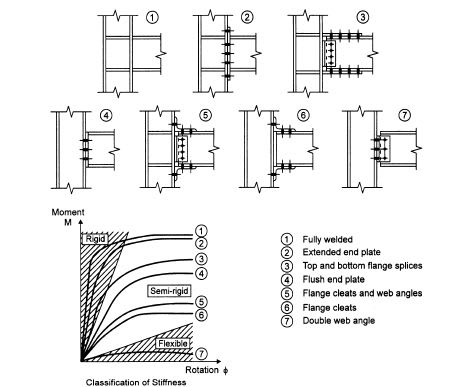
I will suggest to look ( SEMI-RIGID JOINTS IN STRUCTURAL STEELWORK Springer-Verlag ) and semi-rigid
connections handbook by W.F. Chen
The following picture depicts the concept taken from the above reference book

-
1
- #16
I believe that there should a textbook discuss such concepts which will be helpful for fresh graduates especially.
Along your professional life, you will encounter many things that are not covered by the "textbook", or taught in school, however, continued learning can overcome this shortchange. You can read books that cover special topics, such as HTURKAK suggested above, or simply ask around, just as you are going through here now. I don't recall many things I've read from the textbooks in my college days, but I remember well when I found an answer myself, or a professor, a colleague, told me so.... Good luck on growing up in this rather complicate profession.
- Thread starter
- #17
- Status
- Not open for further replies.
Similar threads
- Question
- Replies
- 4
- Views
- 5K
- Question
- Replies
- 9
- Views
- 8K
- Replies
- 6
- Views
- 9K
- Question
- Replies
- 6
- Views
- 9K
- Replies
- 4
- Views
- 3K


