Continue to Site

Eng-Tips is the largest engineering community on the Internet

Intelligent Work Forums for Engineering Professionals

  • Congratulations KootK on being selected by the Eng-Tips community for having the most helpful posts in the forums last week. Way to Go!

U-Bolt Connection 1

Status
Not open for further replies.

Robert1217

Structural
Nov 6, 2020
1
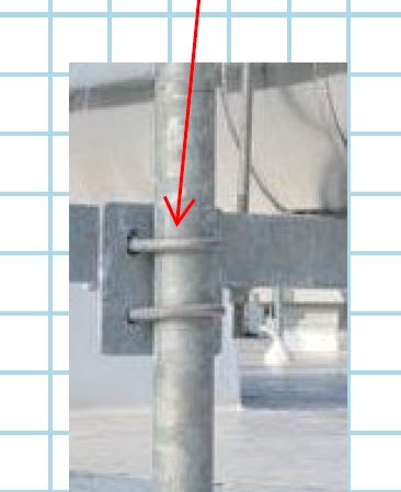
Hi. I'm hoping someone can help me design a U-Bolt Connection. I've got a steel structure supporting HVAC duct on top of a roof. The contractor is hoping we can sit the duct on angles. The angles will be welded to plates and the plates will be U-Bolted to schedule 40 pipe. I'm not sure where to begin with analyzing this and was hoping someone could give me some references or advice. Thanks in advance
image_musiaa.jpg
 
Replies continue below

Recommended for you

Didn't we go through this before? And didn't we conclude that these u-bolt connections have no reliable rating.

= = = = = = = = = = = = = = = = = = = =
P.E. Metallurgy, consulting work welcomed
 
Other than the reliability issue addressed above, you should size the u-bolt for combined vertical shear and longitudinal thrust (tension), assuming rigid connection.
 

Maybe there is something in there...
These are used almost exclusively in telecommunication applications. I always have imagined the pipe slipping through the U-Bolt connection, but:
a) There is always a double nut so the nut should remain locked tight
b) It seems highly unlikely it's just a straight vertical slip failure, and more a slip caused by rotation. In that case, one bolt has to give, but the other does not necessarily give.
c) There is almost always an attachment above the U-Bolt that prevents full slip

Design the friction force like a slip-critical connection on a galvanized surface? I'm not saying it's great, but it's used so widely in an industry that you have to step out of the comfort zone to rationalize it.
 
This type of u-bolt clamp relieve some reliability concern. For heavy duty applications, I've seem teeth on the clamp parts to bite into the pipe walls. From personal experience, most often, the problem with the clamp is upon removal rather than direct drop off :)

image_yngatu.png
 
I really don't think you can "design" or analyse these sorts of things.

What are you going to use for a torque figure on the nut? Do you really think the installer is going to carry around a torque wrench?? No, he's going to just keep tightening it until it doesn't move. And if it does it will be tightened a little bit more.

Get real. These sort of connections have been around for decades without anyone analysing this sort of thing.

But much better to use the backing plate as shown in the photo above.

Remember - More details = better answers
Also: If you get a response it's polite to respond to it.
 
This seems like kindof the realm of working with unistrut. Torque is pretty critical using most of their connections. Maybe check out some of the OSHPD documents for mech/electrical bracing.
 
Don't understand why you don't just drill a hole through the angle and then through the pipe and stick a bolt through it.

You can work out the shear load on the bolt with some accuracy compared to this.

Remember - More details = better answers
Also: If you get a response it's polite to respond to it.
 
LittleInch said:
Don't understand why you don't just drill a hole through the angle and then through the pipe and stick a bolt through it.

Because you need field adjustability, and match drilling every duct support is very slow.

It's also often necessary to make tweaks to the height of duct supports during and after assembly, in which case you might wind up with holes that don't align, or you might wind up having to try to drill a new hole that half overlaps with an existing hole, and then you wind up wasting a ton of time.

Frankly I'm a little surprised this is something that's even being analyzed. While I agree that establishing a true reliable limit capacity for a connection like this is difficult, in my experience the loads applied to connections like this are typically much, much smaller than the practical capacity of the joint (real loads of a few hundred lbs at most, compared to a joint capacity of a couple thousand lbs).

I've installed hundreds of pipe and duct supports using this method and never had a problem, and I've also never had an engineer who cared to evaluate them. Unless you've got really enormous ductwork going in, in my opinion it's not necessary.
 
swinney - I know that. But you could line it up with the U bolts first and get it spot on and THEN drill it to stop it slipping anywhere. Or weld it and then remove the U clamps

The only way to analyse it is to do a full clamp design which is OTT.

It is fine for low forces, instruments etc, but structural steel work?? I would have found another way myself.

Remember - More details = better answers
Also: If you get a response it's polite to respond to it.
 
If you can get your hands on a TIA-222-H code (telecom industry), there is a section (4.9.11.3) that quantifies the slipping resistance and twisting resistance of u-bolted connections.

I'm sure the code's not applicable to a building, but at least you could get an idea of capacity from a recognized source.
 
LI- I don't disagree with your point but I'm not sure I'd consider small gauge galvanized angle duct supports as really 'structural'. Yes, it's supporting a load.. but there's not really any major life safety concern as far as I can see. I've seen it done this way almost all of the time and never had an EOR question it. Being in a major metro area which has very tight code compliance and inspections, if an inspector raised the concern I'd start to worry, but that's never happened either.

If you strap the duct and then match drill and bolt, your installer is doing three times the work; that's even worse than just trying to match drill and bolt.
 
Why not using a plate through the pipe and welding the plate with the angle?
 
Status
Not open for further replies.

Part and Inventory Search

Sponsor