Continue to Site

Eng-Tips is the largest engineering community on the Internet

Intelligent Work Forums for Engineering Professionals

  • Congratulations waross on being selected by the Eng-Tips community for having the most helpful posts in the forums last week. Way to Go!

Umbrella Roof Geometry and Fabrication 1

Status
Not open for further replies.

RFreund

Structural
Aug 14, 2010
1,880
I'm trying to better understand how the roof pieces for an umbrella roof are fabricated. I understand that they are rolled in a single direction and that they are roughly triangular. However, I've also seen references to "gore segment" from IFRs (here) which seems to make sense to me but I'm not sure if it applies here. Here is an example - Let's say I want to fabricate a roof plate. Tank diameter is 50' and umbrella radius is 60. There are 24 segments. There is a 10' diameter compression ring. The dimensions of the sheet steel are as follows:
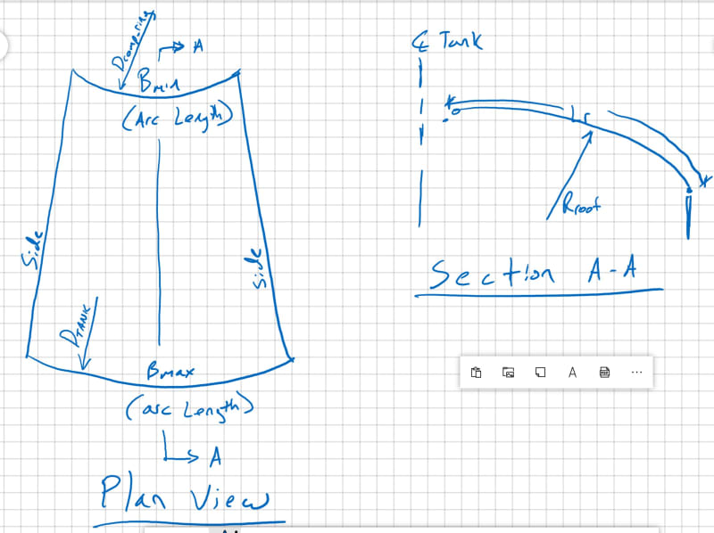
Umbrella_Steel_Roof_Tank_Geometry_oufh5v.jpg


Lr = 20.781' (arc length of sheet steel)
B.max = pi*D.tank/24 = 6.545'
B.min = pi*D.comp_ring/24 =1.309

My question becomes - should the sides of this plate be curved when viewed in plan view or straight? Curved would be like a gore segment (see here). Or, since the plates are only rolled in one direction, is this not required? I suppose the plates will be lapped so there is some tolerance, so I'm curious to know what is "typical" and what is "exact".
 
Replies continue below

Recommended for you


- The two sides SHALL be curved , bottom straight..

- The umbrella roof composed of plates rolled in one direction only,

- If there are 24 segments ( each segment has 15 degr. in plan ) , you will get icosikaitetragon ( polygon having 24 sides) at every horizontal section.

- For plan view, divide the gore say ten sections , calculate the corresponding width and plot these widths..It is easy in CAD.

- Consider similar method for segmental bends . Your segments would be similar with red painted piece.


 https://files.engineering.com/getfile.aspx?folder=c56852af-f192-4dc4-b10a-00cb8115aa47&file=umbrella.jpg
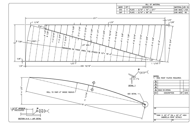
The sides can be straight if you are OK with non-uniform radial laps, this may be OK depending on the actual geometry. for instance, in the attached drawing, the sides of the roof plate curve about 3/8", which could reasonably be ignored IMHO.

40_Umbrella_Roof_Plate_Details_nc7kfr.jpg


One way to do this:
In CAD, draw the roof in plan and elevation and put these directly in line, one above the other.
The plan will be a circle with a bunch of radial lines, straddle the horizontal centerline.
The elevation will be a bunch of arcs that start at the tank shell and meet at the middle.
Subdivide the arc into equal lengths (say 12" for this discussion).
Draw vertical lines through these points to the plan view.
Trim these lines by the edges of one plate segment.
Pull these chord lines out, separating them by 12".
Connect the ends to form an arc.
Compare this arc to a line drawn between the end points of the first and last chord lines.
Decide if the difference between the arc and the straight line is significant.
 
Thanks for the responses. Very helpful. Also in my example case the difference between straight and curved is about 1/2" which seems pretty negligible given they would be overlapped.

One question - would this drawing be the same for a true sphere/dome as it is for a umbrella.
Not sure why I'm having such a hard time wrapping my head around this.

Thanks again!


No, a true dome would have curvature in all directions and the development of the plates is different.

Take a look at an umbrella, then at a balloon with radial lines drawn on it?
 
How would the procedure differ? Intuitively I agree, but I'm not sure why I can't picture this.


The above procedure only works because the straight lines are actually straight and planar in real life for an umbrella roof, not a dome roof.
 
I would like to remind some points,

- The definition of Umbrella Roof;


- I have checked with hand calculation , the difference between straight and curved is negligible , however, the end should be straight . If you make a curved end, the mid point will touch to the top angle but the two corners will not..

- The Maximum radius = 1.2D ..In this case , R= 60' and D= 50' which is the allowable max.

- I do not have any idea for the roof loading and design pressure but in the case if CA is applicable and heavy loading , the plate thk . could be a problem .( shall not be more than 13 mm.)

- I have attached the following fig. from the book Guide to Storage Tanks and Equipment ( By Bob Garner )

umbrella_dome_qgmcnl.jpg


Good Luck..
 
I make curved edges so the roof plate lands in the same place on the top angle around the tank. If you make it straight, it will walk off the top angle or require an adapter plate. I just include the adapter plate with the roof plate.
 
Thanks again for the additional information.

At first, I was thinking that the edge should be "radiused" as I originally showed and as IFRs has explained. But then when I think about this more, I'm starting to agree with HTURKAK. If the plate is "radiused" when viewed from plan, then the plate edges would lift unless the plate is "rolled" in the second direction which by definition is should not be. However, maybe the plates are flexible enough where this is done in the field?

HTURKAK said:
I have checked with hand calculation, the difference between straight and curved is negligible
- Is there a mathematical expression for this that you could share? This might help me come to terms with this easier. Again, I know it to be right, but I can't explain it. I imagine a cone roof which would have straight sides to the plate. Then I imagine curving that plate and I can imagine the seam coming apart, but I think that's because I imagine it turning into a sphere. Anyway, thanks again for your input.

Edit:
At the compression ring:
I believe that the plate butts into the face of the ring, but please correct me if I am wrong. Therefore, this plate would be radiused and if viewed in elevation, there would be a small arc(the ends being slightly higher than the middle). Correct?
 

The easiest way is , to work with CAD. You may also develop a spreadsheet using the rules of geometry and trigonometry. I attached picture of my hand calc sheet.

EDIT: I have calculated the difference between straight and curved is less than 7 mm for one side which seems negligible if the joint is lapped with say 50 mm..
Good luck..
 
 https://files.engineering.com/getfile.aspx?folder=39c1f986-8181-4a72-828f-5c434883c4a2&file=UMBRELLA_ROOF_KALKULAT_0964.jpg
I use a curved edge to keep the roof plate sitting on the top angle. Yes it is not substantiated by pure math or geometry but the minor difference is quite acceptable in the field. Especially when you consider that there is a lap joint that touches the rim. Ordinary field welders will scoff at a mere 1/8" or 3/16" of "fit up" needed. We need to stay in the real world here! Storage tanks are just big tin cans that sometimes are not worthy of complicated, detailed FEA or other analysis when simple hand calculations suffice.
 
Status
Not open for further replies.

Part and Inventory Search

Sponsor