Continue to Site

Eng-Tips is the largest engineering community on the Internet

Intelligent Work Forums for Engineering Professionals

  • Congratulations IFRs on being selected by the Eng-Tips community for having the most helpful posts in the forums last week. Way to Go!

Unable to mesh layer by layer in surface geometry 1

IcarusAero223

Aerospace
Mar 10, 2024
10
Hi all, I would appreciate any advice for this little problem I'm having. [bigears]

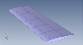
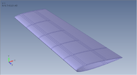
I'm modelling composite wing thats modelled with surfaces in SW and exported as parasolid into Femap (Photos included).
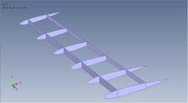
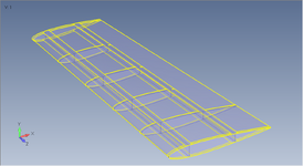
I organized the model into layers: 1. Skin and 2. Internal (spars and ribs). But when I go and mesh surfaces in certain layers, my mesh gets pulled from the other layer into the current active one.

Example: I mesh all of the skin with different assigned properties, and when I switch the layer to mesh the ribs and spar webs, upon meshing the first surface of the rib/spar, all surrounding skin surface mesh shows up in the 2. Internal layer!. (only mesh of the surfaces that share edges gets pulled)

I tried the Geometry > Surface > NonManifold Add command but it didn't help the problem.

So my question is, how do I keep mesh in it's appropriate layer without it switching layers?
 

Attachments

  • whole model.png
    whole model.png
    63.1 KB · Views: 6
  • skin layer.png
    skin layer.png
    66.4 KB · Views: 6
  • internal layer.png
    internal layer.png
    19.3 KB · Views: 7
  • free edges.png
    free edges.png
    84.9 KB · Views: 6
Replies continue below

Recommended for you

1) but wouldn't you want that (the skin sharing nodes with the spars and ribs) ?

2) I prefer to work with groups, you should be able to mesh a group without interacting with other groups (unless you want to).

3) if nodes are moving around on you, I'd mesh the spars and ribs, separate the surface sharing nodes, embed these into the skin surfaces and see how it goes.

4) I'm sure there are smarter ways to do this ... like meshing the surface with a single element (or something else ... separating the surface mesh from the sub-surface structure, and then have some smart thing redistribute the surface loads onto the sub-surface structure.

5) You know you can distribute the CFD loads (from the CFGD mesh) onto your (completely different) FEM mesh ?
 
Dear Icarus,
Please note: one entity (say one node or element) only belong to ONE layer, instead one entity can belong to multiple groups: this is critical to understand.

How do you plan to assure continuity in displacements?: merging nodes is the classical method, so you need to STITCH surfaces to have one curve between surfaces, so merging nodes will be perform automatically, and this is incompatible with separation of skin in one layer, and internal ribs in another layer, etc..: skin & ribs share the same curve, this is the effect of stitching surfaces, either using GEOMETRY > SOLID > STITCH command (valid only for SKIN), or using GEOMETRY > SURFACE > NonManifold-Add.

The picture with FREE EDGES is telling you that the geometry is not properly stitched: this is a typical issue when importing geometry from CAD systems with GAPS between surfaces that causes the Non_anifold-Add command to fail.

I run all in one layer: I sew all surfaces for SKIN using GEOMETRY > SOLID > STITCH command, please note this command do not support joining T-JOINT surfaces, the guilty is the Parasolid engine. For this reason we have in FEMAP the NonManifold-Add command: but this command is less robust that STICH one, so make sure to have coincident curves between surfaces with zero gap to success in the stitching action.

Also, take a look to DEFAULT MERGE TOLERANCE from TOOLS > PARAMETERS command, is critical!!, because affect not only to node merging during meshing but also to geometric operations like stitching: Femap determines the default node merge tolerance based on overall model size. The number is 1/10000 of the model box diagonal (think of the model box being an invisible box that completely encapsulates every entity in the model).

merge-tolerance-femapv2412.png

Alternatively you can run GLUE EDGE-TO-SURFACE, see my blog:

wing-geometry-cad-model.png


wing-mode1-animated.gif


Best regards,
Blas.
 
1) but wouldn't you want that (the skin sharing nodes with the spars and ribs) ?

2) I prefer to work with groups, you should be able to mesh a group without interacting with other groups (unless you want to).

3) if nodes are moving around on you, I'd mesh the spars and ribs, separate the surface sharing nodes, embed these into the skin surfaces and see how it goes.

4) I'm sure there are smarter ways to do this ... like meshing the surface with a single element (or something else ... separating the surface mesh from the sub-surface structure, and then have some smart thing redistribute the surface loads onto the sub-surface structure.

5) You know you can distribute the CFD loads (from the CFGD mesh) onto your (completely different) FEM mesh ?
Only after making this post I realized the shared curves and relevant surfaces need to be in the same layer.
I'm new to Femap so the whole idea of Groups vs Layers is still new to me. Coming from Abaqus, I figured Groups are Display Groups (for postprocessing) and Layers are more like Sets.

I tried using Groups but when meshing my mesh wouldn't show up, unless there is a way to solve this?

Dear Icarus,
Please note: one entity (say one node or element) only belong to ONE layer, instead one entity can belong to multiple groups: this is critical to understand.

How do you plan to assure continuity in displacements?: merging nodes is the classical method, so you need to STITCH surfaces to have one curve between surfaces, so merging nodes will be perform automatically, and this is incompatible with separation of skin in one layer, and internal ribs in another layer, etc..: skin & ribs share the same curve, this is the effect of stitching surfaces, either using GEOMETRY > SOLID > STITCH command (valid only for SKIN), or using GEOMETRY > SURFACE > NonManifold-Add.

The picture with FREE EDGES is telling you that the geometry is not properly stitched: this is a typical issue when importing geometry from CAD systems with GAPS between surfaces that causes the Non_anifold-Add command to fail.

I run all in one layer: I sew all surfaces for SKIN using GEOMETRY > SOLID > STITCH command, please note this command do not support joining T-JOINT surfaces, the guilty is the Parasolid engine. For this reason we have in FEMAP the NonManifold-Add command: but this command is less robust that STICH one, so make sure to have coincident curves between surfaces with zero gap to success in the stitching action.

Also, take a look to DEFAULT MERGE TOLERANCE from TOOLS > PARAMETERS command, is critical!!, because affect not only to node merging during meshing but also to geometric operations like stitching: Femap determines the default node merge tolerance based on overall model size. The number is 1/10000 of the model box diagonal (think of the model box being an invisible box that completely encapsulates every entity in the model).

View attachment 5572

Alternatively you can run GLUE EDGE-TO-SURFACE, see my blog:

wing-geometry-cad-model.png


wing-mode1-animated.gif


Best regards,
Blas.
Blas, thank you very much for taking the time to write this very extensive and informative answer! I figure the only solution for this type of geometry is to have it in one layer and separate sections using Groups.
But let's say, hypothetically, is it possible for two surfaces to share 2 edges, one belonging to one and other to second one, in 2 layers, with edges being connected in some way?
 
But let's say, hypothetically, is it possible for two surfaces to share 2 edges, one belonging to one and other to second one, in 2 layers, with edges being connected in some way?
Of course, YES!, we have another resource very powerful in FEMAP: MESH CONTROL EXPLORER!! (new feature of FEMAP V2022.1, DEC 2020).
NOT need to stitch or sew surfaces, with MESH CONTROL EXPLORER surfaces remains isolated, but FEMAP is able to perform a number of different tasks, including specification of options for mesh propagation, visualization of slaved surfaces for solid meshing and/or mesh approaches on surfaces, and determining if curves are paired by a mesh approach and/or can be paired based on proximity when mesh sizing.

7_2_16-Tools-Other-Windows-Mesh-Control-Explorer-dlg.png

Take a look to the following video:

Please note:
  • For small/medium complexity models: I run both SOLID STITCH & NonManifold-add commands, creating one sheet body, so ALL in ONE layer.
  • For large models: a cargo ship, the structure of an airplane, etc.: MESH CONTROL EXPLORER, not need to stich surfaces, all remains independent, is FEMAP who add relations betwen curves to allow mesh sizing propagation and node merging, OK?.
The following pictures explains the workflow (see my blog: https://iberisa.wordpress.com/2020/12/27/nuevo-femap-v2021-1-diciembre-2020/):

• Resultant mesh when meshing isolated surfaces when MESH CONTROL EXPLORER = OFF: mesh is not coincident.

mesh-control-explorer-femapv2021_1_off.png


• Resultant mesh when meshing isolated surfaces when MESH CONTROL EXPLORER = ON: mesh is fully coincident, and node merging is automatically performed.

mesh-control-explorer-femapv2021_1_on.png


This is a great feature of FEMAP to mesh complex surface geometry with 2-D Plate/Shell CQUAD4 elements, enjoy!!.

Best regards,
Blas.
 

Part and Inventory Search

Sponsor