Eng-Tips is the largest engineering community on the Internet

Intelligent Work Forums for Engineering Professionals

Unbraced length for compression design of steel box top chord in a warren arch pony truss bridge

Status
Not open for further replies.

ThoF

Student
Oct 31, 2023
3
0
0
CO
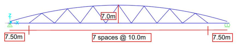
Hi, im designing a pony truss highway bridge with a total span of 85m, the truss is warren type and top chord have an arch form with 7m rise. i have done a 3D finite element model and the buckling factor (obtained with eigenvalues) is more than 1, then i think this is ok, but when im designing the top chord for compression, which unbraced length i have to use? if someone know i will appreciate the help. The floor beams of the bridge are hinged in their ends except for the first and last floor beam. The warren have no post elements and the diagonals does not coincide with the floor beams.
 
Replies continue below

Recommended for you

You need to apply a (probably large) factor on the eigenvalue buckling load (reduce it) to account for imperfections and eccentricities, per the applicable code. Eigenvalue analysis can greatly over estimate actual buckling loads.

Show a picture of the truss design to get better help. (paste an image in, not an attachment)
 
Captura_rktebd.jpg


This is the main truss, the bridge is skewed and floor beam are independet of the main trusses, my question is about the unbraced length, other engineer tell to me that i have to use the total lenght of the top chord for calculatin factores compression strenght
 
For buckling about the vertical axis (movement in the lateral direction), the unbraced length is the full 85+ meter length of the top chord.

That's why you don't typically see pony trusses for spans that long; the top chords would tend to become very wide in order to reduce the kL/r (effective length / radius of gyration) to an acceptable value.

Edit: More often, the upside down permutation of that shape is used, sometimes called an inverted bowstring.
 
I understand but, what about this theory that says that the top chord is like a beam with intermediate elastic springs, due to the diagonals and the so called U-frame
 
The frame action of the "U" comprised of the deck and the diagonal truss chords is a nice theory, but I don't believe there's ever been enough confidence that a real bridge superstructure would perform like the theoretical predictions, even initially.

Additionally, the designer would have to consider the possibility vehicle collision, that could not only disrupt the frame action, but also induce the eccentricity that would initiate a progressive failure that would quickly lead to collapse of the entire superstructure. In short, bridge designers have been reluctant to rely on that theory when they would be responsible for the lives lost if the bridge fails.

Longer span truss bridges, as far as I am aware, always employ lateral diagonal bracing for the top chords.
 
The theory is only considering displacement and stiffness in the plane of the truss. The problem is that any slight sideways perturbation of the top chord will lead to lateral buckling at loads way below a theoretical eigenvalue buckling load.
 
N_euler = pi^2*EI/L_e^2

You usually decide on L_e then work out N_euler. But you know N_euler from eigenvalue analysis so use it to calculate L_e. Then use design code to work out design buckling capacity which will be lower than N_euler.

 
Status
Not open for further replies.
Back
Top