Ally0138
Petroleum
- Aug 30, 2017
- 9
Hi,
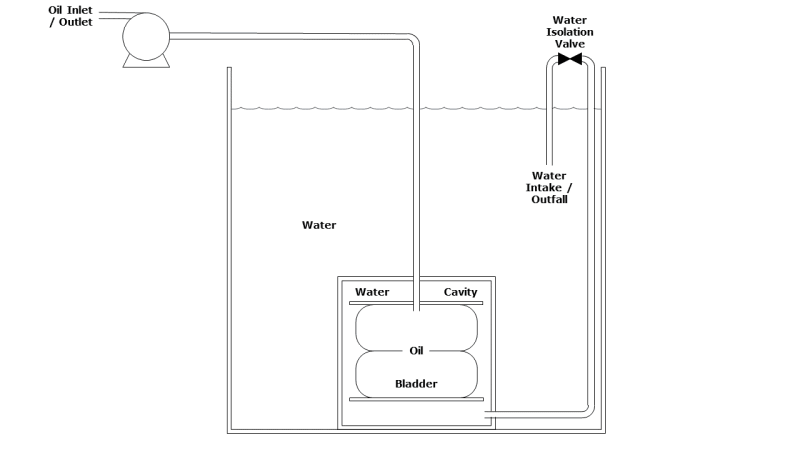
I have tank which consists of an inner flexible bladder contained within an outer metal shell. The whole tank is submerged in water. The inner bladder contains oil which is transferred in / out via a pump located above the waterline, circa 3 m above the base of the tank. The cavity between the inner bladder and the outer shell is filled with the same water that surrounds the tank. The outer shell is completely watertight, with the exception of a single water intake / outfall line, which rises from the base of the tank to an isolation valve just above the waterline and then drops back down into the middle of the water.
Diagram:

Under normal operation, the isolation valve will be open, allowing water to flow freely in and out of the tank outer shell / cavity as the oil bladder is emptied / filled.
Questions:
1. What I'm trying to understand is what will happen if the isolation valve is left in the closed position and an attempt is made to pump oil out of the bladder. Intuitively, I expect that as the volume of the oil in the bladder decreases, since there's no water flowing into the cavity to fill the volume vacated by the water, the pressure in the tank will drop, which will in turn cause a drop in NPSHa to the oil pump. How could I go about estimating the extent of the pressure drop in this case?
Here's where I'm confused: There's normally no vapour in the tank, it's all liquid phase (at least to start with) and pressure in a liquid is proportional only to depth / height of liquid column. But if we have a fixed volume of liquid and pump some of it out, with nothing flowing in to take its place, shouldn't the pressure in the tank drop?
2. Is there a potential issue with positioning the water isolation valve above the waterline? I.e. the water is effectively being siphoned out of the main tank / reservoir into the tank cavity; could we lose the siphon and suck a load of air into the cavity? (Presumably this won't be an issue if the water line is initially filled [I'm not sure how this will be achieved] and the intake is positioned sufficiently below the waterline?)
Thank you in advance,
Ally
I have tank which consists of an inner flexible bladder contained within an outer metal shell. The whole tank is submerged in water. The inner bladder contains oil which is transferred in / out via a pump located above the waterline, circa 3 m above the base of the tank. The cavity between the inner bladder and the outer shell is filled with the same water that surrounds the tank. The outer shell is completely watertight, with the exception of a single water intake / outfall line, which rises from the base of the tank to an isolation valve just above the waterline and then drops back down into the middle of the water.
Diagram:

Under normal operation, the isolation valve will be open, allowing water to flow freely in and out of the tank outer shell / cavity as the oil bladder is emptied / filled.
Questions:
1. What I'm trying to understand is what will happen if the isolation valve is left in the closed position and an attempt is made to pump oil out of the bladder. Intuitively, I expect that as the volume of the oil in the bladder decreases, since there's no water flowing into the cavity to fill the volume vacated by the water, the pressure in the tank will drop, which will in turn cause a drop in NPSHa to the oil pump. How could I go about estimating the extent of the pressure drop in this case?
Here's where I'm confused: There's normally no vapour in the tank, it's all liquid phase (at least to start with) and pressure in a liquid is proportional only to depth / height of liquid column. But if we have a fixed volume of liquid and pump some of it out, with nothing flowing in to take its place, shouldn't the pressure in the tank drop?
2. Is there a potential issue with positioning the water isolation valve above the waterline? I.e. the water is effectively being siphoned out of the main tank / reservoir into the tank cavity; could we lose the siphon and suck a load of air into the cavity? (Presumably this won't be an issue if the water line is initially filled [I'm not sure how this will be achieved] and the intake is positioned sufficiently below the waterline?)
Thank you in advance,
Ally
