The following is assuming that the installation is subject to the National Electrical Code. I am also assuming that the conductors in question are copper.
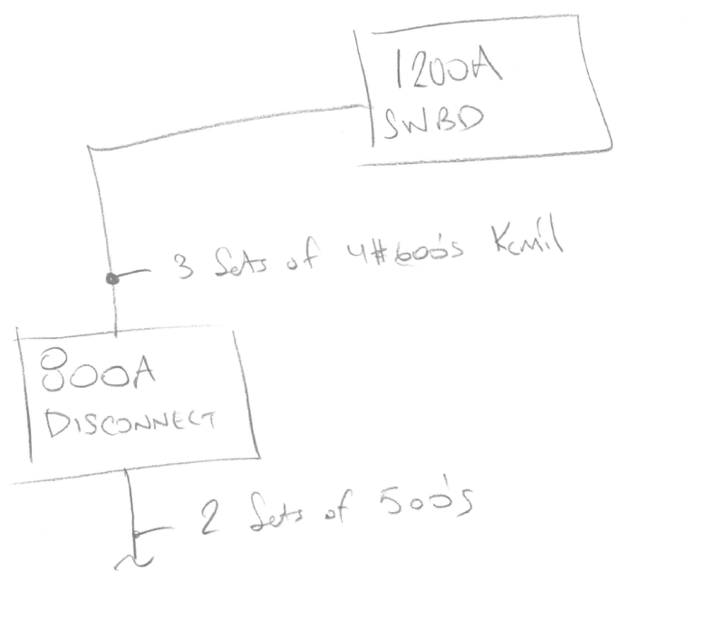
1. On the line side of the 800A disconnect switch, two sets of 500kcmil conductors results in an ampacity of 760A. Using the "next size up" rule in the NEC, 800A fusing is acceptable.
2. On the load side of the 800A disconnect switch, three sets of 600kcmil conductors results in an ampacity of 1,260A - much higher than 800A. There may be a legitimate reason for this. Maybe the conductors were upsized to contend with voltage drop. Maybe the load-side conductors are installed within a high ambient temperature environment and needed to be derated. Maybe it is anticipated that the 800A disconnect switch will eventually be replaced with a 1,200A disconnect switch in response to future, added loads.
3. There are no issues, from a Code perspective, with serving a 1,200A switchboard from a disconnect switch fused at 800A. As long as the rating of the switchboard's bussing equals or exceeds that of the upstream overcurrent protective device, the installation is acceptable. The inverse scenario, serving an 800A switchboard from a disconnect switch fused at 1,200A, is a Code violation.
4. Ultimately, feeder conductors need to be sized to accommodate the load. Generally, their ampacity must equal or exceed the summation of 125% of the continuous load and 100% of noncontinuous load. Demand factors, the presence of motor loads, voltage drop, ambient temperatures, and other issues play a role, as well.