Continue to Site

Eng-Tips is the largest engineering community on the Internet

Intelligent Work Forums for Engineering Professionals

  • Congratulations KootK on being selected by the Eng-Tips community for having the most helpful posts in the forums last week. Way to Go!

Understanding Buckling Factors 1

Status
Not open for further replies.

Alves21

Structural
Mar 4, 2020
16
Good morning, Everyone.

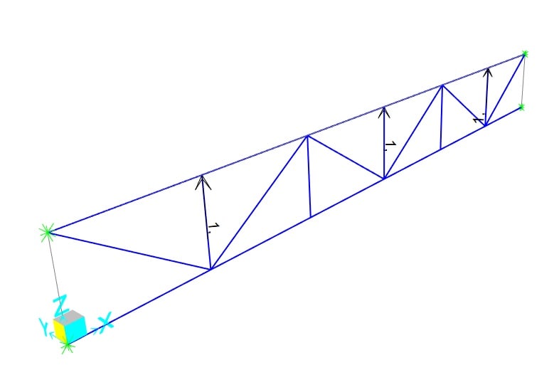
I am trying to understand buckling factor analysis results. I've made this 11m truss and considered both top and bottom chords will be conected to a column. I have considered translation in all directions as fixed and rotation in the x axis restricted too. My analysis is made with a self weight Load and three uplift loads.
2_smtx6f.jpg

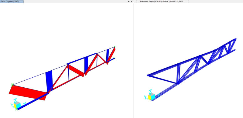
For the results of the first mode I have this
1_q02drj.jpg

Buckling factor of : -53.542
From my understandment, what this means is that for this mode buckling would be based on reverse loading.
Then I have the second mode:
3_hwkar3.jpg

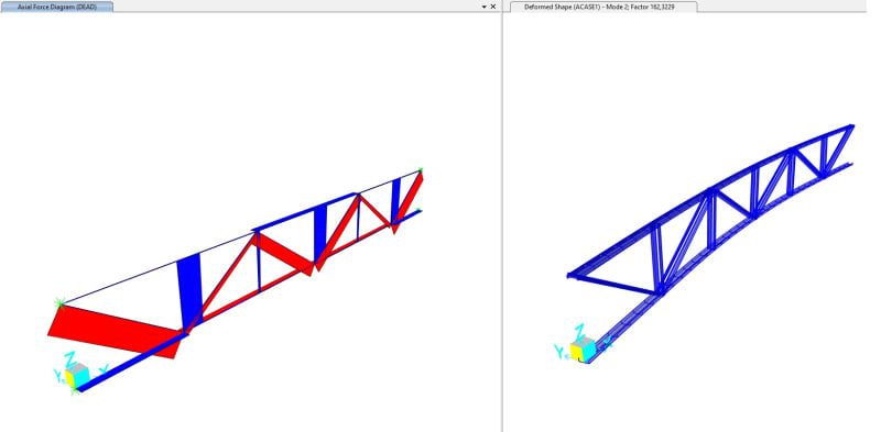
Buckling factor of : 162.3229
And the compression on the bottom chord is: 0,25kN
This means that for my bottom chord the Critical buckling load Ne is equal to: 0,25*162,3229 = 40kN

I would like to know if my understandment of those factors are at the right direction or if I am missing something.
 
Replies continue below

Recommended for you

I don't know what software you are using. But from my experience with different software software your conclusion seems ok.
If you are unsure, use a simple model like a single column with pinned supports. That you can check with a simple hand calculation.
 
At one end of each chord, you need to allow displacement in the x-direction. Otherwise the chord axial forces will be incorrect.

Your load pattern has three 1.0 kN (kip?) upward loads. The -53.5 factor means that SAP2000 thinks buckling will occur when there are three 53.5 kN loads pointed downward. That's consistent with your third figure which shows the top chord buckling laterally.

What is your estimate of the chord axial force that would cause the chord to buckle? it should be straightforward to estimate with a manual calculation. With this problem, I would expect the top chord to buckle about the vertical axis at approximately the Euler buckling load. It's "critical" (ha) to come up with some way to verify what SAP2000 is giving you.
 
Perhaps I know them by a different name, but what are "buckling factors"?
 
Buckling factors are the number you multiply your load by to cause elastic buckling, in an eignen buckling analysis. For OP, note this won't consider inelastic buckling, and a theoretical solution is generally better.
 
I have never seen a negative factor. I could imagine it being generated when there's nothing in compression, though my software just just reports no solution. But this is a truss with compression elements presumably. Why doesn't it solve the positive solution? Seems like an error.

Canwesteng, what do you mean by a theoretical solution?
 
Sorry, theoretical is the wrong word entirely. I mean a published solution that is a blend of theory and empiricism. For example, AISC essentially has correction factors accounting for residual stresses and inelastic effects baked into their equations, but the equations are based on theory. I thought there was some publication that did something similar for truss tension chord buckling.
 
steveh49 said:
I have never seen a negative factor. I could imagine it being generated when there's nothing in compression, though my software just just reports no solution. But this is a truss with compression elements presumably. Why doesn't it solve the positive solution? Seems like an error.
A negative eigenvalue ("buckling coefficient", "buckling load multiplier") implies that the system is in tension at such a load multiplier. Such eigenvalues can be found with discrete spring models (post-buckling causes reversal of load direction) or if the load causes tension and the eigenvalue analysis is performed despite that. Physically, they don't make much sense (buckling occurs during compression), but that's the explanation.

canwesteng said:
I thought there was some publication that did something similar for truss tension chord buckling.
Most standards require combining eigenvalue analyses (idealized perfectly elastic bifurcation buckling, which never happens in real life) with buckling curves that incorporate residual stresses from welding, bow imperfections, non-linear elastic/plastic effects etc. into the design buckling value. In Eurocode, the buckling curves are combined with critical loads from eigenvalue analysis to give a reduction factor to be multiplied with pure axial compression resistance.
 
centondollar said:
A negative eigenvalue ("buckling coefficient", "buckling load multiplier") implies that the system is in tension at such a load multiplier. Such eigenvalues can be found with discrete spring models (post-buckling causes reversal of load direction) or if the load causes tension and the eigenvalue analysis is performed despite that. Physically, they don't make much sense (buckling occurs during compression), but that's the explanation.

Physically they do make sense. A truss system as well as a bunch of other systems will have some members in compression an others in tension. The negative values are just the load reversal cases which depending on the nature of the load may be quite relevant.

Software that I use you can set upper bounds and lower bounds for the eigenvalues. I typically set zero as a lower bound.
 
I am not familiar with this type of analysis, seems pretty robust. Every truss I have analyzed has been performed using first principles and basic mechanics. When do you find this type of analysis useful?
 
MotorCity said:
I am not familiar with this type of analysis, seems pretty robust. Every truss I have analyzed has been performed using first principles and basic mechanics. When do you find this type of analysis useful?

Eigenvalue buckling analysis is a neat tool. The theoretical formulation with the geometric stiffness is fairly straightforward.

In my experience, it can give some weird answers. That doesn't mean the answers are wrong, but it's definitely not a "take what it gives" kind of analysis. One needs to do some side calcs to make sure the answer is believable.

Little experiments go a long way. What about the question of a negative factor in this thread? I just made a SAP2000 model of a 20 ft tall HSS5x5x1/4 column with fixed base and free at the top. Shear deformations turned off. 1 kip at the top, pointing up. The buckling factor is -19.877. With K = 2, the Euler buckling load is 19.88 kips. That took a total of just over five minutes start to finish.
 
human909 said:
Software that I use you can set upper bounds and lower bounds for the eigenvalues. I typically set zero as a lower bound.

What would this do in a case like I mentioned a minute ago? I'm wondering if the zero approach might cause it to miss some modes.
 
271828 said:
What would this do in a case like I mentioned a minute ago? I'm wondering if the zero approach might cause it to miss some modes.
A lower bound of zero will miss many buckling modes. But if you don't have load reversal then they are irrelevant.
 
Interesting. I've always had to define the reversal case if needed, and think I'd still do it even if automatic were an option. In this case, I'd carefully check if any other helpful default settings are enabled that may affect the results.
 
Status
Not open for further replies.

Part and Inventory Search

Sponsor