Got another one for ya'll, this time it has to do with resolving the loads through gable end wall bracing.
I've tried my best to methodically lay out my understanding of how this works and I'm hoping to get some feedback in the areas where I'm wrong.
I'm not sure what post I saw this, but I know that some of you have expressed that truss bracing is more of a 'good practice' type thing through historic trial and error, and that it's difficult to prove exactly how some of this stuff work. I think that's a fair enough conclusion in some situations. I'm trying to simplify this for my own peace of mind.
I got an image from the FEMA website that illustrates a gable end truss, and the roofing components. I figured this is a good place to start. Each component is labeled and I've provide a list of these components and my understanding about their purpose.
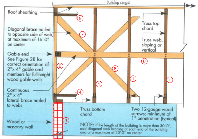
1. Truss web.
2. Gable end truss.
3. Discontinuous wall.
4. Flatwise 2x4 continuous bracing attached at each truss bottom chord/
(Continuous lateral restraint, CLR) Prevents ouf-of-plane buckling of chord due to compression (uplift). Holds truss plumb while lateral loads travel through the bottom plane of the truss.
5. Flatwise 2x4 continuous bracing attached at each truss top chord/
(Continuous lateral restraint, CLR) Prevents out-of-plane buckling of chord due to compression (gravity). Holds truss plumb while lateral loads travel through the top plane of the truss.
6. 2x4 continuous web bracing/
Continuous lateral restraint, CLR) Prevents out-of-plane buckling of web due to compression.
7. X-brace,(Stability bracing) braces top part of gable end truss, where the vertical projection of the gable end is acting as a simple span beam, spanning up and down.
8. X-brace,(Stability bracing) braces bottom part of gable end truss, where the vertical projection of the gable end is acting as a simple span beam, spanning up and down.
Now, assuming the gable end truss has applied lateral load, and treating the vertical projection of this truss as a simple span beam, I've traced the load path of the applied wind load. Each part is labeled according to my first image.
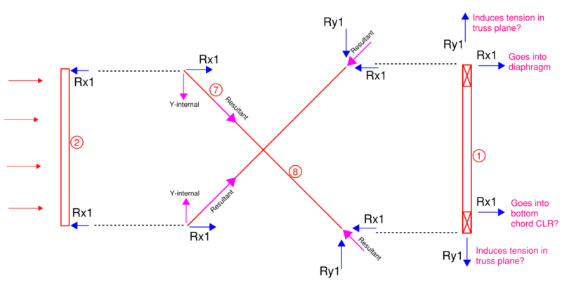
I'm not sure if I'm done something wrong, but the end reactions at the 2nd inset truss appears to be very similar to the original reactions as the gable end truss. My questions are:
1. For the 2nd inset truss, do you have to report these opposing y-reaction forces to the truss manufacturer?
2. If Rx1 goes to the diaphragm and bottom chord CLR of the 2nd inset truss, how is this any different than omitting the x-bracing in the first place? Without x-bracing, couldn't you nail the bottom chord CLR to the gable end truss and end up with the same global reactions?
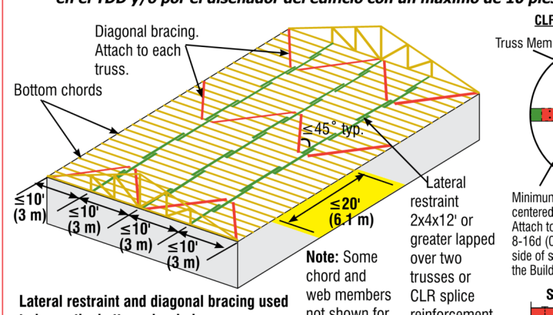
3. I would image the only way to get the lateral load out of the bottom chord CLR is to kick it to the buildings shear walls... or else you'll end up loading a series of truss with lateral loads at the bottom chord. Here is an image of how I assume RX1 resolves OUT OF the bottom chord CLR (the red diagonal bracing acts as a horizontal truss and gets the load out to perimeter walls)
I've tried my best to methodically lay out my understanding of how this works and I'm hoping to get some feedback in the areas where I'm wrong.
I'm not sure what post I saw this, but I know that some of you have expressed that truss bracing is more of a 'good practice' type thing through historic trial and error, and that it's difficult to prove exactly how some of this stuff work. I think that's a fair enough conclusion in some situations. I'm trying to simplify this for my own peace of mind.
I got an image from the FEMA website that illustrates a gable end truss, and the roofing components. I figured this is a good place to start. Each component is labeled and I've provide a list of these components and my understanding about their purpose.
1. Truss web.
2. Gable end truss.
3. Discontinuous wall.
4. Flatwise 2x4 continuous bracing attached at each truss bottom chord/
(Continuous lateral restraint, CLR) Prevents ouf-of-plane buckling of chord due to compression (uplift). Holds truss plumb while lateral loads travel through the bottom plane of the truss.
5. Flatwise 2x4 continuous bracing attached at each truss top chord/
(Continuous lateral restraint, CLR) Prevents out-of-plane buckling of chord due to compression (gravity). Holds truss plumb while lateral loads travel through the top plane of the truss.
6. 2x4 continuous web bracing/
Continuous lateral restraint, CLR) Prevents out-of-plane buckling of web due to compression.
7. X-brace,(Stability bracing) braces top part of gable end truss, where the vertical projection of the gable end is acting as a simple span beam, spanning up and down.
8. X-brace,(Stability bracing) braces bottom part of gable end truss, where the vertical projection of the gable end is acting as a simple span beam, spanning up and down.
Now, assuming the gable end truss has applied lateral load, and treating the vertical projection of this truss as a simple span beam, I've traced the load path of the applied wind load. Each part is labeled according to my first image.
I'm not sure if I'm done something wrong, but the end reactions at the 2nd inset truss appears to be very similar to the original reactions as the gable end truss. My questions are:
1. For the 2nd inset truss, do you have to report these opposing y-reaction forces to the truss manufacturer?
2. If Rx1 goes to the diaphragm and bottom chord CLR of the 2nd inset truss, how is this any different than omitting the x-bracing in the first place? Without x-bracing, couldn't you nail the bottom chord CLR to the gable end truss and end up with the same global reactions?
3. I would image the only way to get the lateral load out of the bottom chord CLR is to kick it to the buildings shear walls... or else you'll end up loading a series of truss with lateral loads at the bottom chord. Here is an image of how I assume RX1 resolves OUT OF the bottom chord CLR (the red diagonal bracing acts as a horizontal truss and gets the load out to perimeter walls)