Hi Folks,
Wondering if anyone can point me in the right direction or provide some useful insights on a phenomena I've frequently observed on sensing lines where entrapped air has been an issue.
What I'm specifically curious about is, how, under certain circumstances, can measured pressure be artificially increased by the presence of air entrapped in a liquid sensing line?
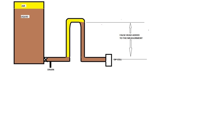
In my current workplace, we have a very simplistic rig where we measure pressure from a static volume of oil (open to atmospheric pressure) via a ~2m length of 12mm hose/sensing line to a remote dP sensor (compensating for atmospheric pressure) that is mounted lower than the volume of oil. During the process of filling/refilling the volume or connecting/disconnecting the sensing line we're able to VERY reliably create a scenario where the presence of entrapped air in the line creates a higher than normal pressure reading for any given volume of oil (or column of oil if you will).
When we prime/purge the line with oil, the pressure ALWAYS DECREASES to a value consistent with the column of oil we're measuring.
This honestly baffles me because I've always considered pressure is pressure is pressure in any fluid until you start dealing with dynamic fluid issues where resonance and flow may start confounding things.
In our case, the system is relatively static when we make these observations and as far as my logic is concerned, air in the line should cause a lower than normal pressure reading due to the mass in the column being reduced and ultimately exerting less pressure on the sensor.
Is there something obvious I'm missing here?
I'd really love for someone to challenge my thinking here or help me understand how this can occur.
Cheers,
Ciao
Wondering if anyone can point me in the right direction or provide some useful insights on a phenomena I've frequently observed on sensing lines where entrapped air has been an issue.
What I'm specifically curious about is, how, under certain circumstances, can measured pressure be artificially increased by the presence of air entrapped in a liquid sensing line?
In my current workplace, we have a very simplistic rig where we measure pressure from a static volume of oil (open to atmospheric pressure) via a ~2m length of 12mm hose/sensing line to a remote dP sensor (compensating for atmospheric pressure) that is mounted lower than the volume of oil. During the process of filling/refilling the volume or connecting/disconnecting the sensing line we're able to VERY reliably create a scenario where the presence of entrapped air in the line creates a higher than normal pressure reading for any given volume of oil (or column of oil if you will).
When we prime/purge the line with oil, the pressure ALWAYS DECREASES to a value consistent with the column of oil we're measuring.
This honestly baffles me because I've always considered pressure is pressure is pressure in any fluid until you start dealing with dynamic fluid issues where resonance and flow may start confounding things.
In our case, the system is relatively static when we make these observations and as far as my logic is concerned, air in the line should cause a lower than normal pressure reading due to the mass in the column being reduced and ultimately exerting less pressure on the sensor.
Is there something obvious I'm missing here?
I'd really love for someone to challenge my thinking here or help me understand how this can occur.
Cheers,
Ciao