Continue to Site

Eng-Tips is the largest engineering community on the Internet

Intelligent Work Forums for Engineering Professionals

  • Congratulations cowski on being selected by the Eng-Tips community for having the most helpful posts in the forums last week. Way to Go!

Understanding the structural system for a slab on grade with point loads and uplift? 1

Status
Not open for further replies.

psychedomination

Structural
Jan 21, 2016
123
Hi there, I am designing a slab on grade for a standard iso shipping container to rest on, where it will remain as a storage container.

This should be quite a simple analysis but I am struggling a bit and trying to understand how the structural system will behave so that I can carry out a conservative analysis and design. I’m not sure if I am going about analysing the structure in the right way, so I can use some help. Essentially I am looking for a lower bound analysis approach, where I can quickly and conservatively do the checks by hand. I don’t have access to FEA and for something this small wouldn’t expect to need it.

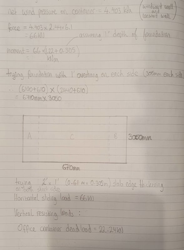
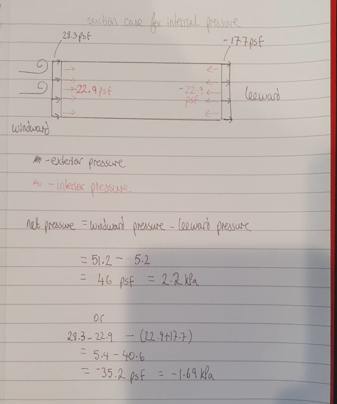
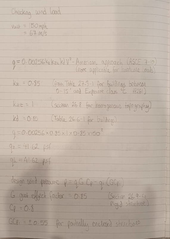
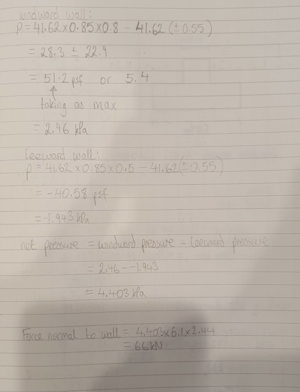
The container has a dead load of 22kN and is subject to a 66kN normal force from wind (acting on the longer side), which results in a moment about the container minor axis of 101kNm. I am just designing the foundation for the container not doing anything to the container itself.

I was thinking of a connection detail for the container and think twist-locks welded to a base plate anchored into the foundation should work fine.

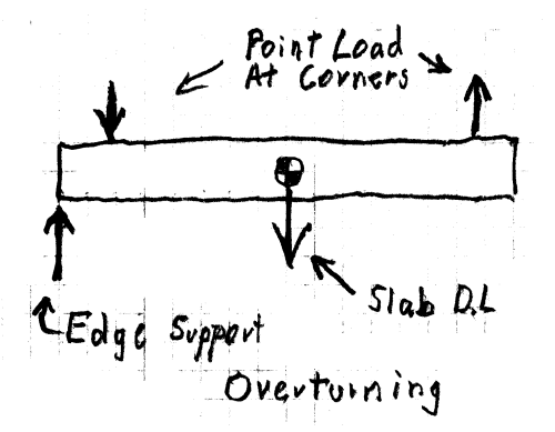
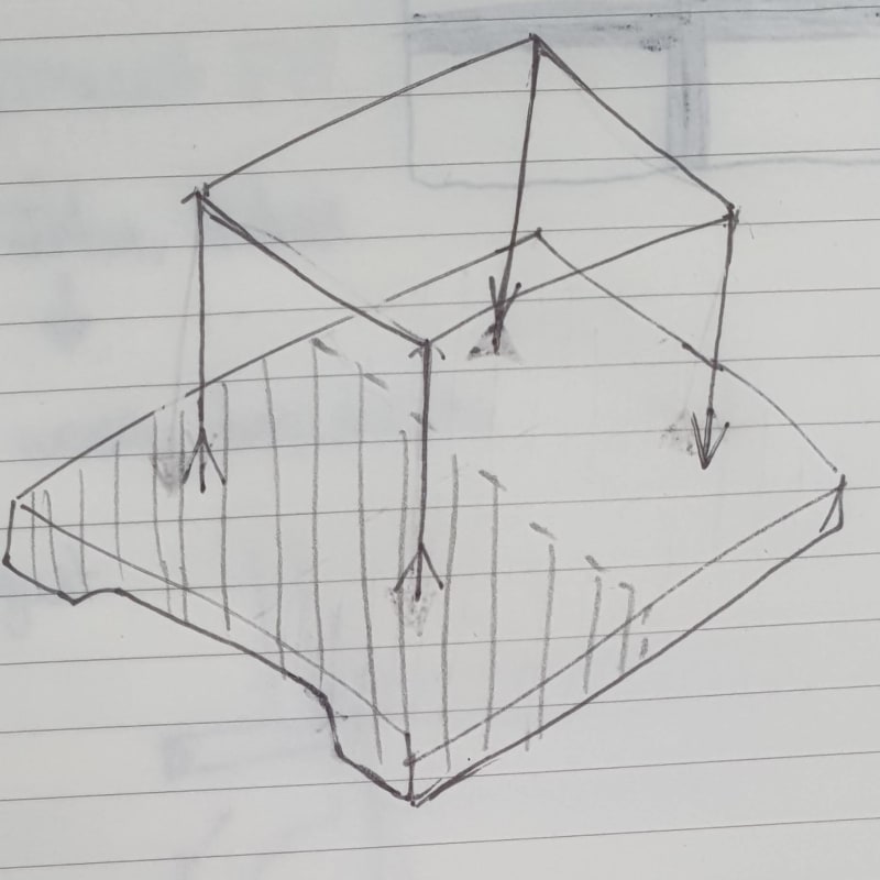
With this system, there will be concentrated loads from the container at each of the four twist-lock locations.

To get the loading on each twist-lock connection, I split the system in half along the long side (effectively splitting the moment in half)… therefore 101/2 = 50.5kNm per side.

I then converted the moment into a couple to get the compression and tensions forces in the front and back twist-lock connections respectively; using 50.5/3.05 = 16.56kN in tension and in compression. For analysis sake say front twist-lock in compression and back in tension.

Load summary :
- Container is 22kN in total so 5.6kN vertical load in each corner twist-lock location.
- Concrete strip footing has a vertical load of 4.47kN/m
- tension (uplift) on one twist lock is 16.56kN
- Compression on one twist lock is 16.56kN

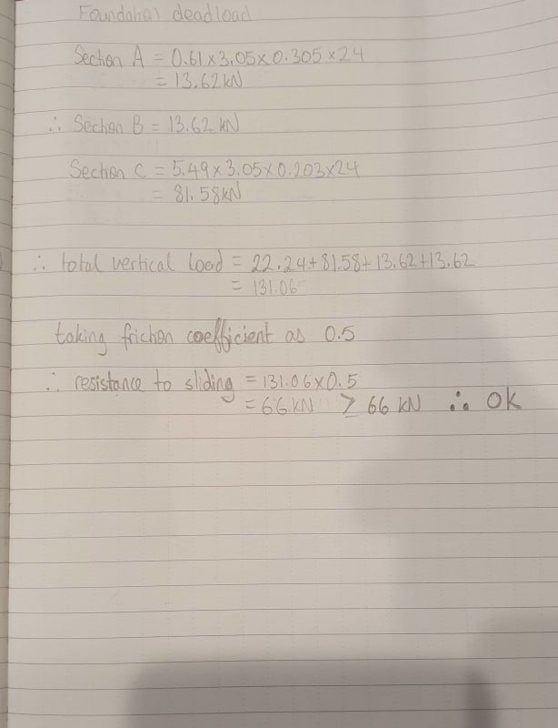
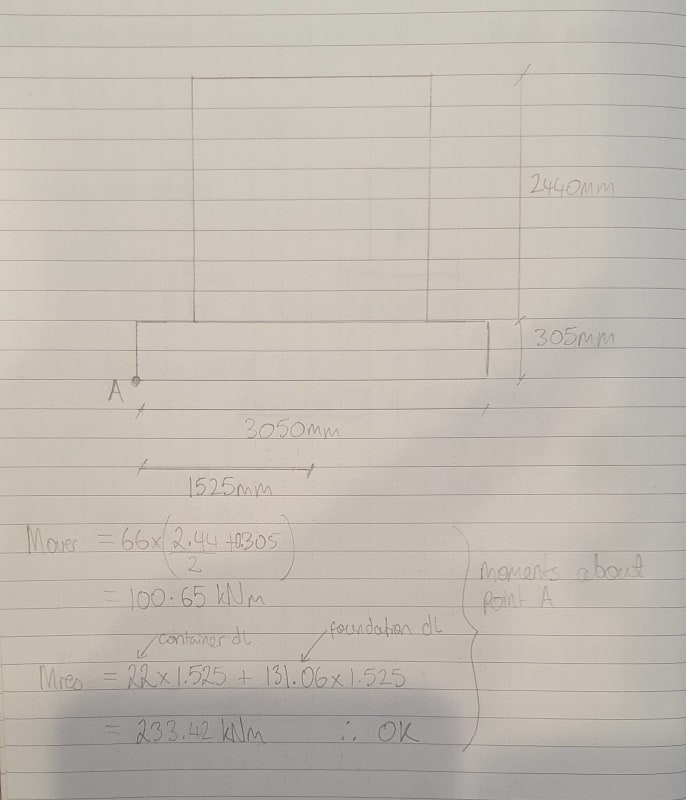
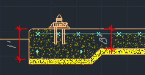
I sized the footing to prevent sliding and overturning but where I’m kind of stuck is how to conservatively calculate the bending moments to design the strip footing, considering the point loads and uplift? I’m essentially viewing it like a beam? See attached sketches/rough calcs.


 https://files.engineering.com/getfile.aspx?folder=ba609742-fff0-41e7-bf30-ff33d41956c3&file=ETS.pdf
Replies continue below

Recommended for you

I think I misunderstood the question, after reviewing the sketch you provided
 
In your calculations, you determined the total vertical load then used that to determine a uniform bearing pressure. You also need to account for the moment (fb = M/S = 6*M/(BL²)). This will be a triangular distributed load going from +fb at one end to -fb at the other end. You then combine this with your uniform bearing pressure from the vertical load.

For the values provided in your calculations, I am getting a bearing pressure reaction that has a significant amount of net uplift at the one end. A properly sized foundation should have only downward reactions. You said that you checked for overturning, so it is because your calculations are not including the dead load from the foundation. (If your uplift reaction is just at the corners, for this calculation and your overturning check you should only be accounting for the weight of the foundation that will be engaged due to the uplift loads in the corners, which is much less than the entire slab width.)

EDIT: Fixed fb formula.

Structural Engineering Software: Structural Engineering Videos:
 
Hi, ProgrammingPE thanks for your comment. I had converted the moment into a couple, which I thought would account for the +force at one end and -force at the other end (therefore taking care of the moment) but based on your comment appears to be the wrong approach.

With regard to your moment bearing pressure formula, I’m not too familiar with that one. Should it be (6*M/B*L^2)?

Total pressure = P/A+(6M/BL^2) = 19.3/(3.05*.61) +/- ( (6*50.5)/(.61*3.05^2))

= a bearing pressure of +64kPa and -43kPa.

Yes, in this calculation I only considered the self-weight of the strip footing portion of the foundation instead of the full foundation weight, I had isolated the strip footing as I had wanted this alone to take the moment and spread the loads. I had included the 8” deep slab between the strip footings to mainly help with the sliding and overturning effects.

I did use the full slab weight in my overturning calculations ( I thought the system would work as one) but I note your point. How would I determine what the ‘engaged portion of the foundation’ is. Would that be half of the foundation as shown in the sketch below?

20210922_174426_-_Copy_dwlyk2.jpg
 
Just a couple quick comments: I have typically used beam design spreadsheets for all sorts of foundations to get shear/moment diagrams. You know you've done it right if you get zero (or close to it) at the supports. And secondly: with that much uplift, another moment condition to check (and I don't know how thick your slab is) is the moment induced by essentially a two-way cantilever from the support. A normal strip footing calc doesn't capture that locally. I'd also be sure the displacements from the uplift (as far as the slab goes) aren't too high.

My 2 cents.
 
psychedomination said:
...designing a slab on grade for a standard iso shipping container...
The container... is subject to a 66kN normal force from wind (acting on the longer side)...

66kN = 14,800 lb. on the side of a shipping container that is 8.5' high x 20' long = 87 lb/ft2 (average wind pressure) ???

Can you show how the 66kN force was calculated?

 
@Warose, thanks I am not getting zero at the supports, which is causing some issues. So I need to figure out how to better analyse the system.

@SRE, the wind load is quite high although this is the first time I used ASCE, so I may have not understood the code correctly. The windload calculations are below :
20210922_210043_-_Copy_jjg1l4.jpg
20210922_210022_upnflu.jpg
 
@Warose, thanks I am not getting zero at the supports, which is causing some issues. So I need to figure out how to better analyse the system.

Remember: in order for this technique to work.....you have to put in everything you used to obtain the equilibrium. In other words, the bearing pressure, concentrated forces, etc.....should all be included to get balance. And yes you are combining these forces when looking at it from the side. For example (just numbers I am pulling off the top of my head): 3 ksf bearing over 10' width? The input should be 30 kips/ft on the "beam". I've found it to be real efficient over the years. If the reaction at the "supports" is near zero (or insignificant relative to the forces applied)......you've got it. It makes a good check.
 
psychedomination - Hmm, 150 MPH... maybe 87 PSF is not that high after all. I'm not current on wind pressure calcs, and am plenty "rusty" on performing any of them, besides. Even using just the basic wind pressure equation I get 58 PSF for 150 MPH... similar order of magnitude. Just for fun, checked to see what is the design wind speed for a shipping container... 180 MPH. No problem there.

Next question, for sliding, can you show the calcs on how the slab resists 66kN (times a suitable safety factor, say 1.5)?
I believe that will be more troublesome to accomplish.

I'll commend you on your cals' format, well documented, orderly and readable.

 
@Warose, Thanks for this comment. I think I am making it a bit more difficult for myself because I was trying to 'split' the system by only considering the strip footing weight, which was messing up the equilibrium. I was trying to analyse the problem as if only the two 1' strip footings were there without the 8" slab connecting the two ends. I was viewing it this way as I conservatively didn't want to consider the strip footings to have any structural contribution from the slab flange.

@SRE Yea it is quite high, and the wind always adds additional complications to these designs. But I guess makes it a bit more interesting.

Now for the sliding, this is an interesting one, mainly because I was reading that the wind speeds stipulated in ASCE 7-10 are already factored as an ultimate load. With this said, I didn't include any additional safety factors to the wind speed given. The sliding resistance is marginally above the sliding force.

I should mention that it would be a rare event to get 150mph winds acting on the structure, which is why I was slightly less conservative when checking the sliding resistance.

And thanks about the calcs, I try to keep them somewhat neat (as you can see I need to revisit them from time to time :) )

20210922_222247_-_Copy_wsxnnp.jpg
20210922_222316_-_Copy_lwa0bs.jpg
 
psychedomination - Good... for now. Coefficient of friction of concrete on soil (0.5), while within reason, seems "optimistic" since friction is the only force resisting sliding. How did you choose that value?

I want to move on to the real reason for my questions, overturning... specifically the proposed slab design for overturning.

 
Yes, it is on the more optimistic side. A while ago, a geotech gave me a range of 0.4 to 0.5 for the friction coefficient values. As the 150mph winds are such a rare event, I considered the higher value.

For the overturning, I assumed that the container overturning would act with the full size of the foundation (which according to ProgrammingPE's post seems to be the wrong approach).

See the calculations for overturning below :

20210923_093423_fvw77f.jpg
 
A couple of notes on your wind calcs.

-You mention Hurricane loads. 150 mph ult wind speed is high, and appropriate for some coastal regions, but ultimate wind speeds in other areas prone to hurricanes approach 200 mph. Just thought I would mention it.

-Is there a reason you are running with partially enclosed? Will the unit by open all the time?

-For combined (windward + leeward) wind, the internal pressure should be equal and opposite, so it will cancel out in the combined case. I think you currently have it additive. This matters less for enclosed structure, but will make a big difference for a partially enclosed structure.

-Note that the wind pressures provided by ASCE7-10 are ultimate-level pressures. Generally foundation analysis and soil bearing are looked at at service-level loading (ASD) in the US since bearing is given as an "allowable net bearing" or something similar.. Depending on your soil parameters and common practice (I am unsure of your country of practice) you may be able to multiply your wind pressures by 0.6 for soil bearing checks.

-As a reference, I would expect wind pressures (combined windward + leeward MWF 150 mph ult) to be around 45 psf total (ultimate pressure).
 
psychedomination - Review RWW0002's post, 45+ PSF is more what I would expect for 150 MPH. The 58 PSF I got from the basic equation is essentially an upper bound.

Don't discount probability of "high" (150 MPH) wind speeds, it happens. I have some first hand experience with structures designed for hurricanes and have been in a few, but that's another story.

Back to overturning. IMHO, the slab design required to resist overturning is going to override both wind pressure calcs and sliding. Under wind loading, the entire slab tends to be lifted off the ground. For "high" wind speed and optimistic assumptions (e.g. no safety factor allowance), the slab is just barely supported by soil. Here is my concept of a free body diagram of a simply supported slab on the verge of uplift:

Edit: I see a mistake in my sketch, the slab dead load is a UDL not a point load.

Overturning-FB-500_dqfmeh.png


Note that two things are going on. The shipping container is trying to overturn on slab and the slab is trying to overturn on the soil.

To resist this load, I doubt that the proposed 8" slab, with what looks like a layer of welded wire fabric is adequate:

Overturning-Proposed-500_keodlc.png


IMHO, a slab with two rebar mats, top and bottom will be required. The slab has to be adequate for both "normal" loading (no wind) and overturning (with it's point load uplift at the corners). Also two rebar mats will be an asset to resist sliding (the slab being "dragged" by it's corners). Keep in mind that sliding and overturning are happening simultaneously.

The "thickness" of a slab with two rebar mats is driven by external factors:
1) Rebar, top and bottom need concrete cover.
2) Rebar mats have a finite thickness which should not be ignored.
3) Maximum spacing between mats is desired to make efficient use of rebar.
4) For the entire slab to perform adequately, it needs to be some what rigid in addition to strong. Rigidity is obtained by increasing slab thickness.
5) Slab constuctabilty should always be considered.

Overturning-Thickness-500_atsdcm.png


Review all of this, accept it or not (no problem here) let us hear your opinion.
 
@RWW0002 thanks for your comment :

1. I did see the increase to 200mph on the wind map chart in the ASCE, although I am in an area close to North Carolina, so used the applicable wind load there.

2. There is a window and door in this container. I guess I was trying to be a bit conservative in the event that someone left a window or door open in a hurricane/high winds. Although truthfully the container building should be fully enclosed in high winds. A fully enclosed structure would definitely reduce the loading.

3. That's interesting and a very helpful comment. When you say 'cancel out' do you mean as shown below?

It was a bit clearer to me when I drew it out :

20210923_120911_vc3y3r.jpg
 
If this is in N. Carolina yes, use the appropriate wind speed. The following link will give you speed for your specific location if desired. ( Based on your use of metric units and the reference to "American Approach" I was thinking you were out of the US and applying ASCE7-10 to another area.

In or around North Carolina I am 99% sure you should be using IBC load combinations with the appropriate factors for ultimate design (for concrete elements) and ASD (for soil bearing and foundation analysis)

I would likely use enclosed structure for your case, although as your sketch illustrates, the higher internal pressure from partially enclosed is negligible for combined wind(windward + leeward). It will make a difference for roof uplift and pressure on a wall surface, however your approach would be conservative.

Your sketch looks correct to me for the windward+leeward case and your overall wind load is much closer to what I would expect for a 150 mph (u1t) wind speed
 
It is possible to use the entire slab/foundation to resist overturning, but you need to make sure the slab is strong enough to do that. This may be possible with a mat foundation that is reinforced top and bottom, but what you were showing was a slab with WWF that would have to span 22 feet between the point loads which would not have worked. The demands on the foundation would be greatly reduced if you added another attachment point in the middle or moved the attachments a little closer together, but I also understand why you wouldn't want to do that.

The IBC gives some recommended values for coefficient of friction which are lower than 0.5:
Soil_Coefficient_of_Friction_zptd0n.png


IBC 2018, Section 1807.2.3 also requires a safety factor of 1.5 for sliding and overturning, but you do get to use 0.6W.

Structural Engineering Software: Structural Engineering Videos:
 
@SRE Thanks, RWW0002's comments were helpful and the result is that my normal force was essentially halfed. Instead of a 66kN normal force there is now a 33kN normal force instead, which will relieve some of the issues I was previously having with the foundation and greatly raises the safety factors for sliding. You raise an interesting point though about the overturning from the container and overturning of foundation happening at the same time. A mat foundation would definitely work as you suggested (albeit would end up being quite a large foundation). I guess originally I was trying to have just the thickened edges act as beams to take the bending from the overturning,, with the middle slab only there to assist by adding additional weight for sliding. I guess that is what I am struggling to calculate/understand is how the thickened edge strip behaves with the 8" slab on grade when taking the overturning load. It may just be easier for me to simplify it like you mentioned and get rid of the thickened edges and make it a uniform flat slab with two layers of reinforcement.

@RWW0002, thanks I am actually not in the states but my local code interestingly enough says to use the ASCE wind contour map for the eastern portion of North Carolina.

@Dik, thanks that is helpful, I was actually recently looking into installing SMath Studio. I think you've given me further motivation to try it out.

@ProgrammingPE thanks, and your comment makes sense. I was mainly considering the overturning about the short side (~10' between supports). The moment in line with the 22' side would be significantly less. I unfortunately, can't move the connections as they are dependent on the corner casting spacing of the container.
 
The client wanted to use containers for an outdoor movie screen support... they were 3 high, if memory serves, and ballast was added to prevent tipping due to wind exposure... since they were essentially empty. I've used SMath for a decade or so (I think) and find it an excellent program, there are a couple of quirks, but it's a great program... can also use Windows 'snapshots' to paste equations and data... if off the page to the side, they don't print. It's easy to 'cut and paste' to write programs using other program code.

Rather than think climate change and the corona virus as science, think of it as the wrath of God. Feel any better?

-Dik
 
Status
Not open for further replies.

Part and Inventory Search

Sponsor