Continue to Site

Eng-Tips is the largest engineering community on the Internet

Intelligent Work Forums for Engineering Professionals

  • Congratulations KootK on being selected by the Eng-Tips community for having the most helpful posts in the forums last week. Way to Go!

Understanding yielding scenarios in a pipe

Status
Not open for further replies.

Stallionbreed

Materials
Nov 17, 2021
24
I was reading a thread about local plastic deformation and strain hardening effects and there were a couple of comments that I found to be confusing. Below is the link to the thread along with the two comments in question. I provide input below:

Thread:

"No. If the line does achieve some local plastic deformation from pressure reaching at or slightly SMYS, the pipe will not fail. There could be some minor plastic deformation but this does not imply the pipe will fail over time. Actually, in some cases local plastic deformation will result in stress redistribution from local strain hardening effects.
rneill (Mechanical)31 May 10 00:06"


The first part about plastic deformation doesn't mean failure is imminent because the UTS hasn't been reached. I don't understand how the stress is redistributed. It's been a while since i studied materials (chemical engineer major) but i imagine this is because the change in the shape and volume of the pipe shifts forces at different points?

"Since internal pressure is a primary stress, and since primary stresses are not self limiting, if you were to impose a pressure that caused a stress in excess of the actual yield strength of the material (as opposed to the SMYS), you could see a failure mode consisting of gross deformation leading to rupture. The material would start to yield and deform resulting in a reduction of the wall thickness leading to more deformation leading to eventual rupture. However, at the same time this was occurring there would likely be some strain hardening effects so the pipe may be able to tolerate a stress somewhat above it's yield stress before failure became inevitable.

In the event of a secondary stress (a self limiting stress) such as due to thermal expansion or settlement, local plastic deformation will relieve the stress, or redistribute it, and failure would be unlikely. Secondary stresses result in fatigue crack initiation and propagation leading to failure which requires a high number of cycles."


In this second comment i'm having a hard time understanding how the strain hardening effects on the pipe can make the pipe tolerate a stress above it's yield point even though it has yielded.

Lastly, why doesn't a self limiting stress create a failure mode?
 
Replies continue below

Recommended for you

Stress redistribution is accomplished by stresses forming internally to balance applied loads. Assuming things remain motionless, a simple static analysis free body diagram of applied loads and resultant member forces can be developed. Once the member forces are determined, T, internal stresses can be calculated from its resisting force determined by the member's geometric placement within the object divided by its cross-sectional area. T/A. If yield stress is reached, slight movements can change the resisting force in the member, T, and that force divided by area, now A-ΔA also will change. To give a simple example of a tension member. When tension is applied externally, a tension stress St is developed within the member. Due to Poissin stress, v x T, the member's cross sectional area is slightly reduced, therefore stress increases slightly higher than what assuming a perfectly rigid member would indicate. Now St = T/(A-ΔA)
If the angle of the tenstin member changes, becoming more perpendicular to an applied force, the resisting force it supplies against the exterior applied load would increase considerably, which in turn would cause St to increase that much more. That as you know is an example of an unlimited primary stress increase, which may eventually result in the tension member's ultimate failure, if yield stress is reached.

If yield stress is not reached, the change in area is elastic and removing the applied load will return the cross sectional to its original A. If yield stress is reached, cross sectional remains at A-ΔA when load is removed. If load is not removed, ΔA will increase further as elongation continues. St = T/ (A-ΔA-ΔA2) and stress is increased even more. If hardening occurs (yield strength increases) ΔA2 will be less than ΔA1, and stress increase will proportionally reduce with each step. That will eventually approach the hardened yield stress value. If it reaches hardened yield stress, it snaps, if not, a new static equilibrium is reached in a plastic redistribution of stress. If the changes in geometry along the way change the member's resisting force, usually increasing, yielding and finally reaching ultimate stress could happen much faster. Some dynamics might enter the equations.

I think the above answers both questions 1 and 2. Yield stress does not remain constant. Yield stress increases above Young's modulus value, (work hardening) usually getting to a peak value, then reducing somewhat to its final ultimate strength value. Until it breaks, that's the plastic range.

Secondary stress failure.
First, secondary stress is any stress condition arrived at after considering deformation. Not all are self-limiting. Example is a column in a structure that is initially straight and plumb, but a defect in the steel, or where someone drilled a bolt hole causes an internal moment to form as stress from axial load is increased. The internal moment causes some slight bending deformation of the column. If axial load continues to increase, bending stresses are introduced, bending the column more and more. As the bend increases, the axial load becomes more eccentric, further increasing bending stresses. That may continue until yield stress is reached and continue until ultimate stress and column collapse, sometimes at a lower than yield stress value from Euler buckling mode.

A thermal load in a pipe could be applied in the same manner as the structural column above, which could result in pipe failure. But if bending was somehow limited, for example in a horizontal pipe in a pipe rack, increasing the temperature would increase the compression stress in the pipe to yield, giving the pipe a permanent bend, but if the ends of the yielded pipe were held in place by more pipe welded to each end the bend would be pretty much prevented from increasing more and more. If the bent pipe's ends could not move, increasing expansion bending would stop when the pipe reached final temperature. Bending to failure might have been prevented. That depends on the highest stress value reached before motion was arrested. That is the self limiting aspect. A bent pipe, but no stress failure occurred. Only a visual appearance fail.

I think that's all your questions answered. Got any more?


Einstein gave the same test to students every year. When asked why he would do something like that, "Because the answers had changed."
 
First Paragraph:

I agree that stressing the pipe to SMYS will not cause failure since there is a long way to go until the ultimate strength is reached. So at the SMYS the pipe will just reach the point where elastic strain becomes plastic strain. However due to discontinuities where there are stress risers, due to the flow of the load aroud the discontinuity the stress will be greater than SMYS and be in plastic region. Since the material in the plastic region cannot support the load beyond the plastic stress then the width of the plastic region is spread out further from the point of the discontinuity until the stress concentrated load is balanced by the plastic stress. This is what is meant by redistribution of load.

Second Paragraph:

Don't agree since if at SMYS there is still long way to reach ultimate strength considering that SMYS could be the actual yield point - you don't know if it is or not. So beyond yield the stress strain curve becomes flatter but still slopes upward, strain hardening, but still has a way to go to UTS.

Third Paragraph:

In any case of stress whether thermal or not, stess will be redistributed around discontinuities by plastic deformation; however with cyclical stresses such as thermal, fatigue may lead to failure. Thermal stresses do lead to failue of the gross member, not at discontinuities, when allowable bending stress is exceeded which is approxmately twice the SMYS due to the effects of strain hardening of the gross member.

 
What's left after Young's E is highly dependent on the material. Cast iron has nothing, but copper will go a long way past it.

Einstein gave the same test to students every year. When asked why he would do something like that, "Because the answers had changed."
 
Thanks 1503-44. I never had yield stress explained to me like that before. Fascinating

Snickster:

"Since the material in the plastic region cannot support the load beyond the plastic stress then the width of the plastic region is spread out further from the point of the discontinuity until the stress concentrated load is balanced by the plastic stress. This is what is meant by redistribution of load."

I'm sorry this part is very confusing to me. Can you break it down further?

Also, it seems many API pipes have a Yt/St ratio of 0.85. Is there a particular reason for this? Something to do with this discussion?

Thanks!
 
Say there is a discontinuity in the pipe such as a hole for a unreinforced branch connection where the branch pipe cannot take any load. The load that is normally taken by the metal where the hole is can be calculated to be the width (diameter of the hole) times the thickness of the pipe times the global membrane stress in the pipe before the hole at that location. This membrane stress will be due to both longitudinal and circuferential pressure stress and other longitudinal sress due to such things as bending due to weight of pipe between supports. This load will now need to flow around the hole and it will do so around the perimeter of the hole. This is basically what is called a stress concentration factor where the actual stress increases above the global membrane stress that is across the entire pipe crossection at that location. Say that the original global stress in the pipe is just at the yeild point. Therefore the concentrated stress with the load flowing around the hole will cause the metal to be above the yeild stress and will cause the pipe around the hole to go from elastic stess to the plastic stress region as it flows around the hole. For a metal the stress strain curve is basically flat although there is a mild slope upward as the strain increases so that the maximum load that can be transfered through a metal once it reaches the plastic region is basically the value of the plastic stress times the area that it acts on no matter how much the material strains (say it deforms by elongating in tension for a tensile pressure stress). In this case the width of the plastic region around the hole will increase until there is enough crossectional area times the plastic stress value to balance original load plus the extra load flowing around the hole. So the higher the additional load flowing around the hole the wider the plasic region around the hole necessary to balance the load. So the load is redistributed around the hole by plastic deformation/strain of the metal around the hole. In such case the pipe will not fail unless the load is so high that the width of the plastic region at the hole grows to a value that basically extends across the entire cross section. However the width of the area in plastic strain typically does not extend that far beyond the hole since the original global membrane stress in much lower than the yield by design so that not much load has to flow around the hole due to the removed metal of the hole. These stresses around such discontinuities are grouped with secondary stresses and higher allowables stresses are allowed because of the fact that the loads are redistributed and are therfore self limiting rather than leading to gross failure of the member (such as the case for primary stresses that are not self limitin)

It has been a while since I looked at this but I belive I am explaining it about correctly in general, however it is very hard to thoroughly describe verbally without sketches. Hope this helps.

I am not sure what you mean about Yt/St.


I am not sure what you mean about Yt/St.
Me either.
Could you rephrase the question.

Einstein gave the same test to students every year. When asked why he would do something like that, "Because the answers had changed."
 
Snickster, after reading that i drew a sketch and now it clicks! I appreciate you breaking that down further for me. For the record I'm a chemical engineer so some of this material is a bit foggy in my head.

For Yt/St I meant Yield Strength/Tensile Strength. sorry for using the wrong variables.
 
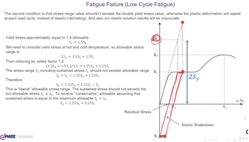
I explained it here Lecture 15
2022-09-02_14-09-05_xvhkkj.jpg


I'm the PASS/START-PROF Pipe Stress Analysis Software Developer
 
Hi Stallionbreed

Here is the way I understand strain hardening in a pipe, once the pipe reaches yield or slightly above yield say by over pressurisation and then the pressure is removed, this leaves a residual compressive stress on the inner face of the pipe. Now once the pipe is pressurised again there is a residual compressive stress to counter act against the tensile hoop stress in the pipe which is generated by the internal pressure. Hence pipes that have been subjected to this process can usually handle higher pressures than it normally would experience. My experience of this was autofrettage in pressure vessels.


“Do not worry about your problems with mathematics, I assure you mine are far greater.” Albert Einstein
 
desert fox what you describe is elastic shakedown which is the exact thing shown in the diagram that Alex M posted just above. Yes this is due to strain hardening phenomenon and stress reversal on load removal and then the reapplication of the load where then the stress will then be within the elastic range on subsequent cycles as you described, as long as the effective stress does not exceed approximately twice the yield stress per the diagram Alex M posted. This is the basis for ASME 31.3 allowable stress values for thermal self limiting stress of 2Sy approx.
 
Stallionbreed:
Another way of saying or thinking about some of what’s been said above, is that the non-yielding mat’l. which surrounds a highly stressed region (yielding or plastic region) tends to constrain or confine the plastic region from growing, by absorbing some of the overstress as it too starts to approach the yield stress. The strain involved in the plastic (yielding process) can’t happen or grow, unless the surrounding mat’l. is further strained (causing growing stress level in that surrounding mat’l.) to allow this expansion. At some point equilibrium and compatibility are generally reached, and the plastic region growth stops. The important engineering design consideration is that some small amount of yielding is generally o.k., but it must be constrained, so it can’t grow unabated, or you can have a fairly quick failure. The definition of failure can be the start of significant yielding, some serviceability criteria, and finally ultimate failure/rupture or some such.

The stress/strain curve that Alex Matveeff shows above is a fairly idealized curve for some steels. Not always shown to exact/full scale along both axes. The horiz. portion (plateau) of the curve is the plastic range, where strain can grow without much increase in stress (the yield strength) unless inhibited/controlled in some way. Then, the further up-sloped portion of the curve is the strain hardening portion of the curve and stress will grow slightly with increased strain due to the strain hardening. And, many steels do not really have a horiz./plastic plateau. Rather, their yield strength is set at a .2% strain offset, and they only have strain hardening shape/slope to their curve right of this point.
 
Status
Not open for further replies.

Part and Inventory Search

Sponsor