Continue to Site

Eng-Tips is the largest engineering community on the Internet

Intelligent Work Forums for Engineering Professionals

  • Congratulations IDS on being selected by the Eng-Tips community for having the most helpful posts in the forums last week. Way to Go!

Uniformly distributed torsion in HSS beam 1

Status
Not open for further replies.

DETstru

Structural
Nov 4, 2009
395
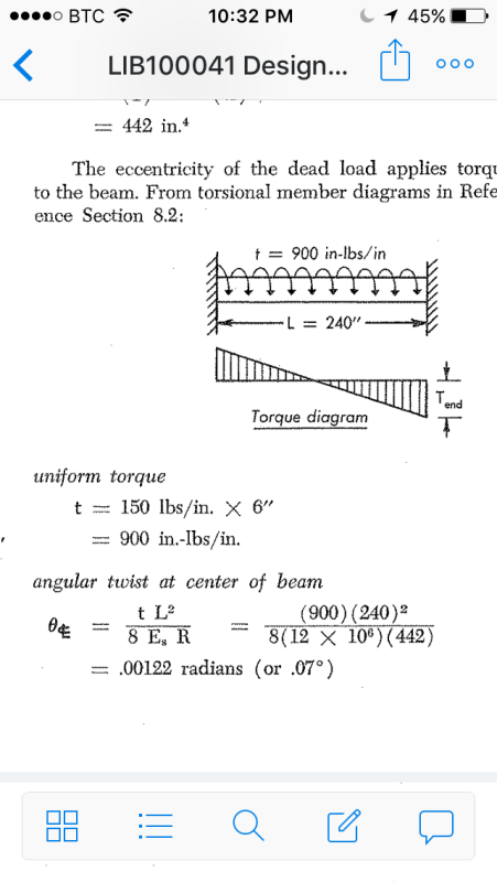
Hi all, I'm designing an HSS member that has closely spaced 4' outriggers along one side of its 21' span (fixed ends). No other loads. I want to determine the deflection by figuring out the rotation of the section. I'm using AISC Design Guide 9 an the graphs in the appendix and assuming a uniformly distributed torque.

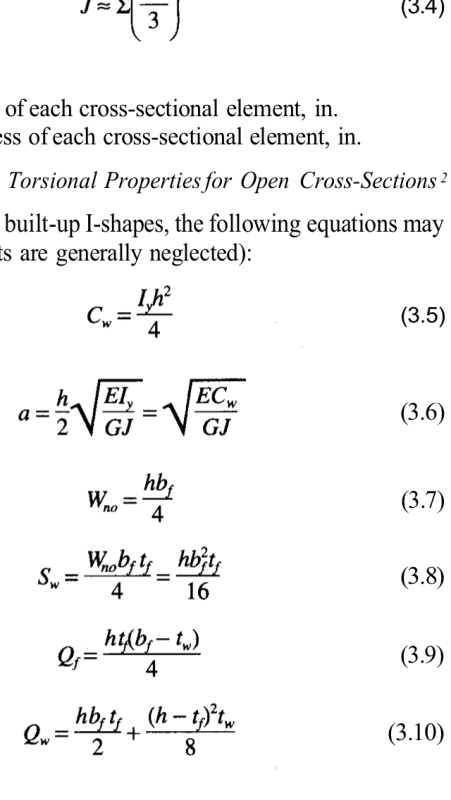
They all reference this torsional property "a" (lowercase), and I don't know what this is. They list it for WF shapes but don't for HSS. What is this value and how do I determine it for an HSS shape?

Thanks!
 
Replies continue below

Recommended for you

Try Page 4, Equation 2.5


Check out Eng-Tips Forum's Policies here:
faq731-376
 
Thanks, the problem with that equation is that Cw is generally taken as 0 for HSS sections (it's not even listed in the AISC tables). That makes a = 0 and the rotation becomes 0 rad.
 
Cw is the torsional constant from the steel book that is situational with every beam size. Where doe sit assume Cw is zero?>
 
"C" (units of in^3) is the Torsional Constant. "Cw" (units of in^6) is the Warping Constant, which is listed for WF shapes but not HSS because Cw = 0 in^6 for HSS shapes.

I'm not sure where in the Manual it says Cw = 0 for HSS shapes but this document ( from CISC indicates it on page 4.
 
With warping off the table, you can just apply TL/JG to your concentrated torques and superimpose the results. A quick excel sheet will make short work of it. No doubt there's a direct formula someplace but I wasn't able to locate it with Google in 30 seconds or less.

It may just be a semantics thing but it's important to recognize that you probably don't have uniform torsion. What you likely have is:

1) a uniform distributed load applied eccentrically and;
2) torsion varying linearly from zero at the middle to maximums at the ends.

I like to debate structural engineering theory -- a lot. If I challenge you on something, know that I'm doing so because I respect your opinion enough to either change it or adopt it.
 
Perhaps:

W X e X L/2 X L / 4

I like to debate structural engineering theory -- a lot. If I challenge you on something, know that I'm doing so because I respect your opinion enough to either change it or adopt it.
 
I have outriggers at 12" on center imparting a 1.5 k-ft torque each. If I could calculate the rotation at the first outrigger, then the second, then the third, etc I would add them until I get to mid span.

My problem is actually calculating rotation. You need "a" to determine the Torsional Function from the AISC DG 9 appendix graphs.
 
KootK, I see your second reply. can you elaborate a bit more? Not sure what that formula is expressing.
 
Torsion of a hollow section is described in detail in "Theory of Elasticity" by Timoshenko and Goodier. An approximate solution can be found using membrane analogy.

For a quick and dirty solution, check "Design of Welded Structures" by Blodgett. He provides a value of R = 2tb2d2/(b+d) in which b and d are the sides of the rectangle formed by the centerline of the HSS walls and t is the thickness.

Then θ = TL/EsR
where T is torque and Es is shear modulus, usually called G and L is the length of tube subjected to a uniform torque. θ is the angle of twist expressed in radians.

BA
 
Thanks BAretired, I'll try that.

Is the "T" a single torque (k-ft) or uniform (k-ft/ft)? I have that text but not with me at the moment.
 
T in the formula is a constant torque. In your case, you will have a constant torque for a length of 4', then a sudden change in torque for the next 4' and so on. Your torque diagram will be a step function with maximum values at the fixed supports.

BA
 
Thanks. I think Blodgett will do the trick (as he many times has). I'll have to look at the chapter to see if this is for fixed ends or pinned.

I'm still confused about how to use the AISC DG 9 method if you have a tube. It works for WF shapes but many of high-torsion applications want to be tubes. You'd think they would indicate the limitation. Or maybe I've just missed something. I sent a note to the AISC solutions center so we'll see what they come back with. I'll update if anyone is interested.
 
The formula is for twist of a rectangular tube of length L subjected to a torsional moment of magnitude T. There is no mention of whether the supports are fixed or pinned. If you want the total deflection of the outriggers, you would need to add the beam deflection to the torsional deflection.

BA
 
OP said:
KootK, I see your second reply. can you elaborate a bit more? Not sure what that formula is expressing

Sounds like you're on your way with Blodgett but I'll answer this anyhow for good measure. I should have divided my previous equation by GJ and that would represent an approximation of the angle of twist at midspan assuming only St. Venant torsion (no warping). Essentially the area under the torsion/stiffness diagram between the supports and midspan.

I like to debate structural engineering theory -- a lot. If I challenge you on something, know that I'm doing so because I respect your opinion enough to either change it or adopt it.
 
KootK, I'm not sure that's correct but I like the number I'm getting from Blodgett so I'm sticking to it!

Thanks everyone for the help.
 
DETstr said:
KootK, I'm not sure that's correct but I like the number I'm getting from Blodgett so I'm sticking to it!

I reviewed Blodgett's most relevant example (#5) of which a portion is shown below. With the following substitutions, it's identical to the formula that I provided above:

W X e --> T
R --> J
Es --> G

Blodgett's R is essentially a single factor accounting for both J and Cw. For open sections the difference between using J and R is huge. For closed sections, it's modest. Notably, for closed sections, Blodgett indicates that tested rotations for closed sections were too small to measure. As such, it's not clear to me why Blodgett assumed R to be an improvement over J for closed sections. To some degree, it depends how one defines J. The formulation included in this document is very simple to calculate and is what I'd probably use: Link

image_u2yoav.png


I like to debate structural engineering theory -- a lot. If I challenge you on something, know that I'm doing so because I respect your opinion enough to either change it or adopt it.
 
OP said:
I'll have to look at the chapter to see if this is for fixed ends or pinned.

It assumes a fixed torsional boundary condition. With a closed section, there's really no such thing as torsionally pinned. We assume closed sections to be restrained against warping which, by definition makes them torsionally fixed.

OP said:
I'm still confused about how to use the AISC DG 9 method if you have a tube.

You don't use it. At least not the case chart business which is intended for use with sections that will be meaningfully affected by section warping behaviour.

OP said:
You need "a" to determine the Torsional Function from the AISC DG 9 appendix graphs.

If you review all of the places where "a" is defined in DG9, you will find that it takes on a value of zero wherever Cw would take on a value of zero (closed sections).

image_fvmdp3.png


I like to debate structural engineering theory -- a lot. If I challenge you on something, know that I'm doing so because I respect your opinion enough to either change it or adopt it.
 
@KootK,
I believe you are misinterpreting what Blodgett intended. The problem is with the symbol 'J' which Blodgett is taking as the polar moment of inertia of a section. The J value in my Steel Handbook is the torsional constant which is quite different than polar moment of inertia. Actually, Blodgett's R is the same (or nearly the same) as the J value for a section.

For open sections such as tees, angles and WFs, J is the sum of d.t3/3 for each flange or web. Blodgett's R value is precisely the same as he lists in Article 2.2-8.

For closed sections such as HSS, the torsional constant J, listed in the Steel Handbook is slightly less than Blodgett's R value which I believe is due to the rounded corners on an HSS. The value of the warping constant, Cw for an HSS is actually zero so Blodgett's R value is intended as the torsional constant which we label J.


BA
 
Status
Not open for further replies.

Part and Inventory Search

Sponsor