Continue to Site

Eng-Tips is the largest engineering community on the Internet

Intelligent Work Forums for Engineering Professionals

  • Congratulations KootK on being selected by the Eng-Tips community for having the most helpful posts in the forums last week. Way to Go!

Uniformly Distributing Point Load from Crane Outrigger 4

Status
Not open for further replies.

aSperling

Structural
May 4, 2016
5
I am working on a lift plan that involves outrigger loads being applied to existing foundations. My max. outrigger load is 75kips and the original building Engineer on Record has indicated that the maximum applied UDL is 2000 psf which is governed by subgrade bearing pressure. Given this I want to distribute the point load over a 5'x8' area. The EOR has indicated that I am to provide calc's to prove that the UDL from the crane outrigger is distributed over the area required.

I have a plan on how I want to do it. From top down I would use the 18" outrigger shoe on a 4' diameter aluminum outrigger pad (honeycomb design, 6" deep section). The outrigger pad would be placed on 4' wide row of 8' long railway ties. The ties would be placed on steel rig mats on the concrete floor.

My intuition tells me this would do an adequate job of spreading that point load out; but how does one go about proving this numerically?

Since the 12" concrete structural slab would be stiffest element can I even count on the 7" thick railway ties assisting in load distribution? Would the concrete slab not need to deflect in order for the load to spread out thru the wood layer? The wood/concrete comparison is the most extreme difference in stiffness; but I am wondering what the principal is that could be used to look at the aluminum/steel layers as well.

Thanks in advance for any guidance on this.
 
Replies continue below

Recommended for you

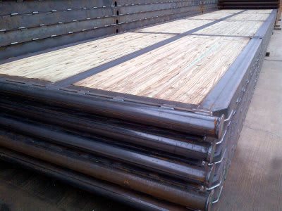
If you have not done this type design before, you're made a pretty good start, but there are problems. I'm not familiar with "steel rig mats", but some work with Google leads me to ask if these are rig mats?

Steel-Drilling-Rig-Mats-400_bsbp1p.jpg


There is no one solution, there can be many ways to get an acceptable answer. Unless another member can help you, I'll get back to this thread tomorrow.


[idea]
 
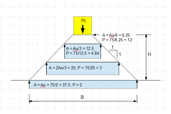
I will throw my two cents at this. One resource is Shapiro's book on Crane's and Derricks but it leaves something wanting on this kind of design. I think the basic principle is to look at the deflection of your cribbing vs the concrete slab and enforce/maintain deflection compatibility at the interface.

image_vee2ld.png
 
Yes, deflection compatibility is the key for anything better than a 45* or 60* spread (which in your case would be prohibitively tall). You may be able to make some leeway from the fact that the 2000psf bearing pressure has an implicit deflection associated. But in most cases there won't be much actual soil data to back that bearing/deflection criteria up, so tread cautiously.

To get the distribution you want/need, you might need to force bearing contact at certain points first rather than relying on uniform contact.

You're right that the railway ties will not be stiff enough distribute the load very much, especially if the slab bears on grade. In the past, I've had my contractor fab up steel flitch plate crane mats to increase stiffness for very specialized cases. Expensive, of course.


----
just call me Lo.
 
Is it 2000psf at top of slab or bottom? That is, can you count the slab's distribution?

Try working from result backwards by applying your target udl at bottom and crane load at top. Calculate deflection then judge if stiffness is adequate.
 
aSperling - When you can return to this thread, maybe you can post some info on the steel rigging mat. It's properties will be needed for the calcs you have been requested to perform.

[idea]
 
I think one very important information is the foot print of the 75 kips load. If it occupies 37.5 sf area, then there is no need to spread the weight out. However, if it is a point load, then you will need a quite thick mat to meet the 2 ksf limit.

image_chmgp7.png
 
Thanks Everyone for your input. Sorry for the late response. Some answers:

SlideRuleEra - Yes those are very similar to the rig mats I would use. They basically consist of 3 - W6x15 beams running longitudinally with approx. 5-1/2" square timber running laterally and constrained by the flanges.

Steveh49 - I am fortunate in this case as the geotech is very well understood. I am inside a waste water treatment plant with the cranes setup. 2000psf is the bearing capacity of the granular base below the structural slab. Ultimately the 24" thick slab is the most effective load distributor in this setup - however I am not rely on it is my issue.

Lomarandil - I was contemplating this. If I were a better understood/more homogenous material than used railway ties it would be fairly straight forward to calculate the deflection at the load then shim the end of the 'beams' up to slightly exceed the calculated deflection at full load. This would ensure contact at the midspan of the beams doesn't occur at the full load and would spread the load out the full length of the ties. If I need to get into it this I may opt to use a row of HSS Section beams in leiu of the ties since the material properties are better understood.

r13 - yes assuming the 1:1 spread as you and Lomarandil put it makes the mat setup prohibitively tall.

GC Hopi - Thank you very much for the reference. This is the exactl problem I am up against.

Thanks again everyone,
 
ASperling:
Is the EoR giving you a hard time on this, or just insisting on a thorough explanation of what you are doing? You might want to study the slab reinforcing, etc., a little, to be sure that you are not placing your grillage in an unfavorable location. This is a relative stiffness problem, sometimes called elastic matching problem, the way you’ve described it. The 12” slab (now you say 24” thk. slab) is a flat pl. on an elastic foundation, and the max. soil load will be immediately below the 4' diameter aluminum outrigger pad. This is where the max. cribbing and slab deflection theoretically occurs.

You can explain how it generally works, with considerable confidence, but several variable are difficult enough to pin down exactly, so that calcs. to a significant degree of exactness are somewhat less certain, so the EoR shouldn’t expect 6 decimal place calcs. But, this is no different than his own footing designs where he assumed uniform soil pressure under a square or rectangular footing, or some such. A reasonable engineering assumption, but not absolutely exact. Don’t forget, that as you calc. your final (avg.) soil pressure you should be able to add 2’ (12” slab thk. x 2) to your grillage size, or is it 4’ now, for a 24” slab.

You might actually be better off just using a second/bot. layer of railroad ties, 8’ x 8’, instead of the stl. rig mat. Then, you have a lower soil bearing load of 1.2k/sf (75/[8x8]), instead of 1.9k/sf (75/[5x8]), and you can more easily explain away any minor variations, apparent overloads. Then, you need one less different type of material making up your grillage, with different materials and material properties and section/structural properties, etc. And, the wood layers will crush a bit, in cross grain compression, which helps even out the loading. That’s kinda the assumption of a stacked wood grillage/cribbing, but pretty tough to quantify. You do want uniform thickness in your supply of ties, so you may want a lumber material which is sawn to thickness. Used ties may be too irregular or spongy.

You might be better off just using a bottom layer of railroad ties, about 5’ x 8’. They don’t have to be absolutely tight, side by side, as long as bending and comp. perp. to the grain are o.k. Eliminate the 4’ dia. bearing pad, it just tends to screw up the works in calcs. and explanation. Rather, make a stl. grillage, from the top down: the 18” outrigger shoe, then a 24” sq. top bearing pl., with some stiff. pls. under it and into the webs of 2 or 3 – 5’ long stl. bms., running parallel to the railroad ties. These 2 or 3 beams bear on two cross beams, each about 2’ in from the ends of the ties. Now, study the deflection on the ties and you should have a more unform loading on the slab, than under the point load using the 4’ dia. mat, in your OP.

 
aSperling - IMHO, you have selected components (outrigger shoe, 4' pad, timbers, & steel rigging mat) that will work... but the order of the components, from top to bottom needs to be changed:

1) Outrigger shoe - Converts the 75 kip point load into a 33.3 kip/ft[sup]2[/sup] UDL.

2) 4' pad - Transforms the 33.3 kip/ft[sup]2[/sup] UDL into a 5.97 kip/ft[sup]2[/sup] UDL.

3) Steel rigging mat - The W6x15s spread the 5.97 kip/ft[sup]2[/sup] UDL along the 8' pad length. Per Lomarandil's comment, the mat starts to spread the load across the width of the pad at a 45[sup]o[/sup] angle. If timber was used for this layer, it's rigidity (to distribute load horizontally with minimum deflection) is inferior to steel.

4) Timbers - Conform to the concrete surface and provide some compressibility, per dhengr. Timber continues the 45[sup]o[/sup] loading spread. If the rigging mat was the bottom layer, both conformance and compressibility are lost.

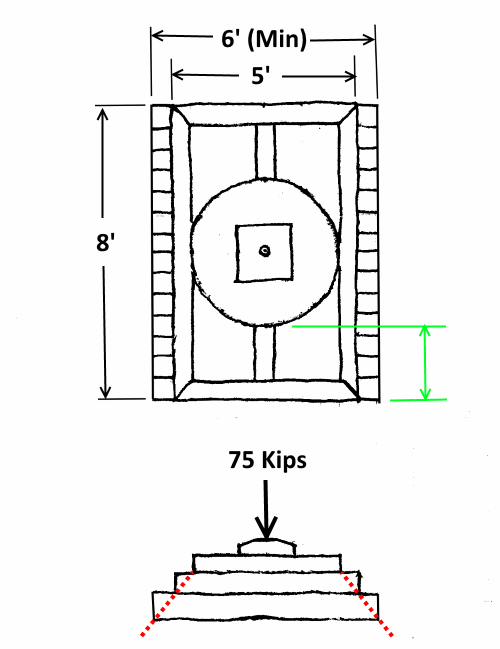
This combination results in the following:

Rig_Mat-500-2_zy2wv4.png


The system can be considered rigid across it's 6' width (marked in red on my sketch).
For the moment, neglecting all the W6 beams, the mat can also be considered rigid for the center 6' of it's 8' length.

Result:​
Contact Pressure Upper Bound = 75 kip / 6' x 6' = 2.08 kips/ft[sup]2[/sup]
and​
Contact Pressure Lower Bound = 75 kip / 8' x 6' = 1.56 kips/ft[sup]2[/sup]

To pin down where the "answer" lies between these two bounds, assume the entire 75 kips is supported by only the center 8' long, W6 (actually, I consider that beam to carry about 80% of the load, the other two W6s about 10% each).
This beam has a load of 75 kips / 8' = 9.38 kip/ft. This assumes beam is uniformly supported by timbers all along it's length, which is not true, but is conservative. The center 4' is rigidly supported, without deflection, by timbers bearing on concrete. Both ends (shown in green on my sketch) are cantilever beams, each with a 9.38 kip/ft load on the 2' cantilever length.
Calculate the deflection at the end of each cantilever. That is the maximum deflection of the entire 8' beam.
I have not performed the calcs, but I bet the ratio of length (8') to deflection is much less than the widely accepted criteria of L/360.

Bottom line, to me, this math exercise indicates the "answer" is much closer to the Lower Bound than the Upper Bound.
I'll say Maximum Contact Pressure ≈ 1.7 kips/ft[sup]2[/sup]


[idea]
 
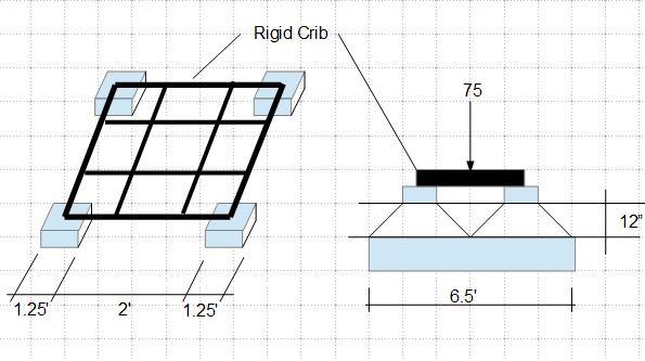
How about this. When calculate the pressure, you should add the weight of crib, the support blocks and concrete. Adjust the dimensions as required.

image_npkpub.png
 
Hey Guys,

Update on this thread. I reached out to another more experienced engineer we work with to provide our final solution. No offense to anyone here; but I have not done many projects of this nature so figured id exercise this option.

We reviewed the design of the 4' diameter aluminum outrigger pads using a finite element analysis. By applying a total UDL of 100 kips on the Circular area of the outrigger shoe and supporting the outside perimeter of the round pad only we found the deflection to only be approx .05" which we identified as being negligible and therefor treated those pads as being fully rigid.

We then spread the load out at a 45degree angle as per my colleges experience which matches the groups comments - for this we used 12" thick timber mats. We relied on the thickness of the floor slab (It was 12" - I incorrectly stated 24" in my other reply. This resulted in the 75 kips reaching an area exceeding the 5' x 8' required.

We used the 6" steel rig mats as 'insurance' and floor protection. Did not rely on them to spread the load out. From what I learned here I think we could rely on them to spread the load out at the same 45 deg. angle.

Attached is a photo of the finished crane setup. You will see a blue tank - we are removing (3) of those which are adjacent to each other.

Thanks everyone for your input; I appreciate it.


 https://files.engineering.com/getfile.aspx?folder=dc10a15f-a28f-495f-b70d-d35a967a3245&file=IMG_1819_(1).jpg
I think you didn't look at the sketch in my last post. The proposed foot print was 4.5'x4.5', and the load distribution dimension was 6.5'x6.5'. So the resulting pressure is 75/6.5[sup]2[/sup] = 1.78 ksf < 2 ksf. The 4' diameter outrigger pad can sit on the support blocks comfortably, provided each of the block is capable of support 18.75 kips concentrate load.
 
You’re spot on R13. That’s exactly how I’d approach it - nice simple calcs too.

Everyone’s far too quick to jump on FEA these days. Young engineers really are losing the feel for numbers (that’s a general rant, not a dig at OP!).
 
IRE,

Thanks for confirming my math.
 
Status
Not open for further replies.

Part and Inventory Search

Sponsor