Hello, I had posted this along with several other questions here, but I wanted to re-post the weld specific question here as it may get some different insight.
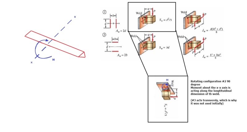
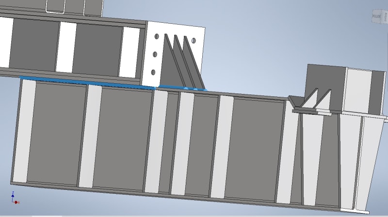
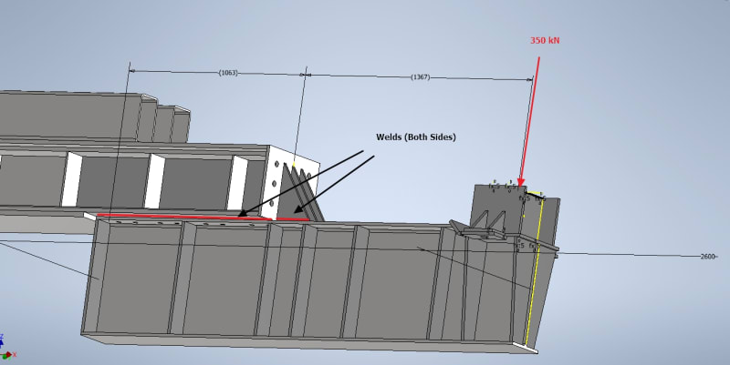
I have a weld and load geometry that I have not been able to find a concrete example on how to evaluate in any textbook or code. I have what is essentially a cantilevered beam cantilevering off another beam, below image best shows the weld geometry with the loads and their dimensions
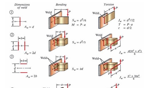
Originally I attempted to calculate the weld stress conservatively by using #2 above for only the overlapping beam section while ignoring the gussets, calculation as per below:
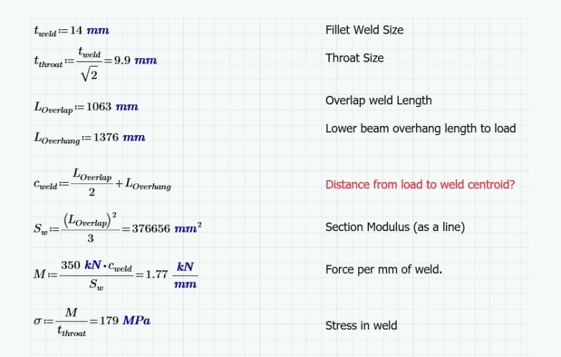
However this stress is too high, (per AS 3990) need to get to .33σut, which is 142 MPa in my case.
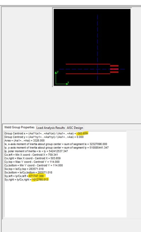
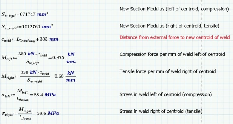
I then went into a deep search on how to add the strength of the gussets to the weld calculation. See Hobert - Welding Formulas and Tables P.17 (P.10 in PDF) to derive any weld shape. Then on P.19 (P.11 in PDF) under 9.3 Example 2 it gives a bit of a worked example of something similar. Following these formulas from these pages I get:
Sw_left = 671747 mm2
Sw_left = 1012760 mm2
I then checked against this structural software [URL unfurl="true"]https://github.com/buddyd16/Structural-Engineering/tree/Python3_migration[/url] got the same values (yay!).
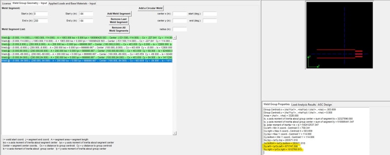
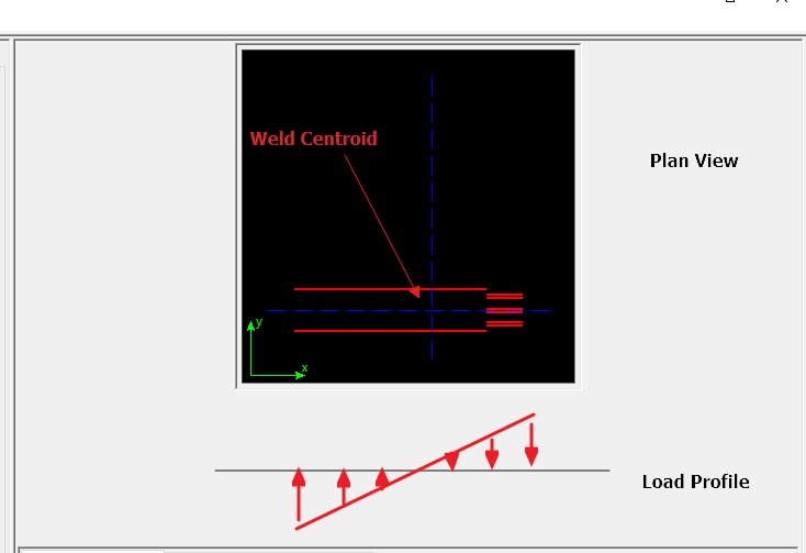
I then re-calculate the two (compressive and tensile) stresses in this weld geometry as follow:
My questions/concerns:
[ul]
[li](Most Important) Is this a valid weld geometry? Never seen any examples in which a weld is situated in this way relative to its load, I believe its still bending about its neutral axis (y-y), but find it strange I haven't seen any configurations such as this anywhere. It may seem that the load will just overload the first part of the weld it comes into contact with and unzip and not actually rotate about its centroid.[/li]
[li]Am I using the right moment arm (Overhang Length + Distance to Centroid) in calculating my stress? or should this be some other distance.[/li]
[li]Are there other stress's missing?[/li]
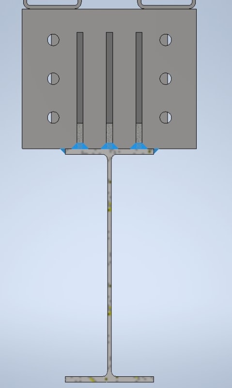
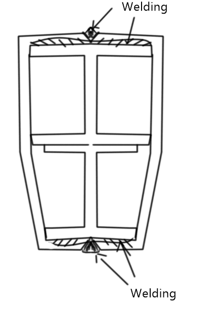
[li]The I-Beam and Gusset welds connect to the same object in the same plane, but their weld legs go in opposite directions (up and down), can I still combined the two?[/li]
[/ul]
“If the women don't find you handsome, they should at least find you handy.” - Red Green
I have a weld and load geometry that I have not been able to find a concrete example on how to evaluate in any textbook or code. I have what is essentially a cantilevered beam cantilevering off another beam, below image best shows the weld geometry with the loads and their dimensions
Originally I attempted to calculate the weld stress conservatively by using #2 above for only the overlapping beam section while ignoring the gussets, calculation as per below:
However this stress is too high, (per AS 3990) need to get to .33σut, which is 142 MPa in my case.
I then went into a deep search on how to add the strength of the gussets to the weld calculation. See Hobert - Welding Formulas and Tables P.17 (P.10 in PDF) to derive any weld shape. Then on P.19 (P.11 in PDF) under 9.3 Example 2 it gives a bit of a worked example of something similar. Following these formulas from these pages I get:
Sw_left = 671747 mm2
Sw_left = 1012760 mm2
I then checked against this structural software [URL unfurl="true"]https://github.com/buddyd16/Structural-Engineering/tree/Python3_migration[/url] got the same values (yay!).
I then re-calculate the two (compressive and tensile) stresses in this weld geometry as follow:
My questions/concerns:
[ul]
[li](Most Important) Is this a valid weld geometry? Never seen any examples in which a weld is situated in this way relative to its load, I believe its still bending about its neutral axis (y-y), but find it strange I haven't seen any configurations such as this anywhere. It may seem that the load will just overload the first part of the weld it comes into contact with and unzip and not actually rotate about its centroid.[/li]
[li]Am I using the right moment arm (Overhang Length + Distance to Centroid) in calculating my stress? or should this be some other distance.[/li]
[li]Are there other stress's missing?[/li]
[li]The I-Beam and Gusset welds connect to the same object in the same plane, but their weld legs go in opposite directions (up and down), can I still combined the two?[/li]
[/ul]
“If the women don't find you handsome, they should at least find you handy.” - Red Green