Continue to Site

Eng-Tips is the largest engineering community on the Internet

Intelligent Work Forums for Engineering Professionals

  • Congratulations cowski on being selected by the Eng-Tips community for having the most helpful posts in the forums last week. Way to Go!

Unusual Canopy Connection 3

dik

Structural
Apr 13, 2001
25,996
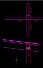
I have an unusual canopy connection with W12x30 beams framing into an HSS 8x8x0.375 column. They connect at different levels. There is a continuation of the beam on the opposite side of the column. I'm planning to field weld 5/8" end plates on the beam ends to the face of the columns as shown. Does anyone have any concerns about this approach? Worked a better approach. Thanks...
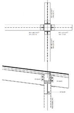
1744343427603.png
 

Attachments

  • 1744340023563.png
    1744340023563.png
    35.7 KB · Views: 22
Last edited:
Replies continue below

Recommended for you

Tolerances on beam length leading to gaps?
The BAR stock should be able to accommodate the gaps, and the bolted clip angle will hold the beam temporarily while welding the BAR material.
 
This could be assumed semi rigid connection rather than rigid. I would prefer the W12 X30 sloped beam is continuous and the HSS column extends to the bottom of sloped beam with a cap plate .
 
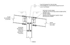
You have a lot of options. Perhaps something like this? or a field-welded similar option?

Running the W12 continuous over the column is always good, unless it interferes with the perpendicular W12. Resolving the flange force at the top of an HSS is going to be difficult, unless the conx plate or beam is continuous.

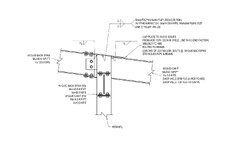
Edit to tack on a shop welded alt for the cantilevers.
Document2.jpg

Shop Weld Alt.jpg
 
Last edited:
At 40 ft-k, the flange plates will bow the walls of the HSS.
 
At 40 ft-k, the flange plates will bow the walls of the HSS.
I'm in the process of determining if the flange plates work, including the axial load. Thanks... I may be back to my end plate solution.
 
At 40 ft-k, the flange plates will bow the walls of the HSS.
How do you figure? Did a quick check against J10-2, J10-4 and Eq 9-29 and it's max is like 40% utilization under those, especially with the flange plate being nearly as wide as the column.
 
How do you figure? Did a quick check against J10-2, J10-4 and Eq 9-29 and it's max is like 40% utilization under those, especially with the flange plate being nearly as wide as the column.
My gut. 40ft-k / 12" beam = 40k load on the weak axis of a 3/8" plate
 
My gut. 40ft-k / 12" beam = 40k load on the weak axis of a 3/8" plate
Depends on whether it's LRFD or ASD. I'm getting the HSS limit states to squeak by with LRFD. ASD, without a doubt, will have major problems and the lower flange plate would have to be made wider and the HSS split into an upper and lower section. Perhaps the "f" in "Mf" is some indicator I'm not familiar with.
 
Depends on whether it's LRFD or ASD. I'm getting the HSS limit states to squeak by with LRFD. ASD, without a doubt, will have major problems and the lower flange plate would have to be made wider and the HSS split into an upper and lower section. Perhaps the "f" in "Mf" is some indicator I'm not familiar with.
It means "factored". Dik practices in Canada, so we use LSD (limit states design, along with the psychedelic) which is similar to LRFD.
 
I am not all that familiar with the checks for this situtation. Are you just checking the tube wall itself or the fact that the deflection of the tube will stress the crap out of the welds that connect it to the plate as the plate will not match the deflected shape of the tube wall?
 
I am not all that familiar with the checks for this situtation. Are you just checking the tube wall itself or the fact that the deflection of the tube will stress the crap out of the welds that connect it to the plate as the plate will not match the deflected shape of the tube wall?
While you're probably right about the true behaviour of the connection, it's not something that is checked under AISC 360-16. Not sure if there is a check in 360-22 for that.

IFAIK you check the connected face for yielding and puching, and you check the side walls for yielding and crippling due to the point load (basically web buckling but for HSS). I'd imagine the deflection that the column face experiences is quite small before it starts yielding, so if you size for yielding it's a non-issue.

The yielding check is also based on an effectice width of the flange plate, so it assumes you are applying the load over a smaller area then what is actually provided which might be another reduction linked to your concern baked directly into the equation.
 
It would be interesting for one the FEA guys here to run this case to see the true joint behavior. I think we will be suprised by the results.
 
How do you figure? Did a quick check against J10-2, J10-4 and Eq 9-29 and it's max is like 40% utilization under those, especially with the flange plate being nearly as wide as the column. The other issue I have is the effect of the transverse plates on adjacent faces.
I haven't finished my SMath program yet, but that was one of the concerns I had. I'll be looking at AISC as part of the work. I still have to include axial loading and clip angle design.
1744408517063.png
 

Part and Inventory Search

Sponsor