Continue to Site

Eng-Tips is the largest engineering community on the Internet

Intelligent Work Forums for Engineering Professionals

  • Congratulations waross on being selected by the Eng-Tips community for having the most helpful posts in the forums last week. Way to Go!

Use and Abuse of Soil Springs 1

Status
Not open for further replies.

MacGruber22

Structural
Jan 30, 2014
802

I have been trying incorporate some of the advice within this seminar (Link), but I am curious of any opinions (affirming or conflicting) with respect to mat foundations. It seems that the concern for varying spring stiffness isn't applicable when mat foundation span to depth ratios are low.


"It is imperative Cunth doesn't get his hands on those codes."
 
Replies continue below

Recommended for you

Soil Springs are easy to use and many structural analysis softwares requires such input thus structural engineers like them. However it is too simplified and many factors are lumped into one Spring constant thus it loses the following important factors: soil nonlinear response, stress path, 2-D and/or 3-D effects,plastic response, etc; Without a proper soil-structure interaction analysis using geotechnical software/analytical method,and a couple of iterations between structural and geotechnical analyses, the results may be far from realistic unless the stress level is low and foundation soils within the influence depth are in elastic stage.
 
Henry - I appreciate and understand your sentiment. Do you have any suggestions regarding varying the spring stiffness? Yes, no, maybe so? Every geotechnical report I have seen, which provided mat foundation parameters, never mentioned varying the subgrade modulus.

"It is imperative Cunth doesn't get his hands on those codes."
 
MacGruber22, for structural design (checking bending and shear for reo)I would at least do halving and doubling the springs; for geotechnical design (working load only) I would provide a set of preliminary springs for structural guys to determine the force at each spring location then work out Spring = vertical load divided by settlement, then ask the structural guys to rerun with revised springs. Normally 1 to 2 iterations would be enough to get a converged settlement. Depending on the scale and complexity of the project, numerical methods may be required for the iterations. Hope this helps.
 
Well for me, the vast majority of soil-spring applications do not require an intense iterative approach using variable nonlinear springs, 3D effects, etc.

The thing is, that for most moderate structures (we do mostly buildings) a structural engineer can do exactly what HENRYZAU suggests above using a parametric approach by bracketing the possible soil-spring ranges....i.e. use a soft spring to design the structure above (a ceiling design based on higher resulting bending/shears) and then use a higher spring stiffness to check soil stresses under that footing.

I've seen over time that the variation of the spring stiffnesses do not always significantly affect the structural design above and trying to develop, and pay for, a high-end "precise" soil-spring model is really not worth it for most moderately sized buildings.

Now if you have a structure that is very sensitive to settlements, and requires a more precise modeling and analysis, then go knock yourself out and buy the more sophisticated information....which I sometimes would doubt would really be that much more accurate anyway.


Check out Eng-Tips Forum's Policies here:
faq731-376
 
The half and double approach is a good first step. However, usually when engineers do this simplified bounding, they apply the scaling factor to all springs.
For large mat-slab foundations and heavy loads on a consolidating clay, you also need to vary the springs under the mat. That is, for long term behavior, the springs at the middle are weaker (lower k) than the springs near the edges. The foundation smiles, as you would expect, simply due to the variation in soil stress distribution ("Boussinesq" effect). If you ignore this (and many designers do), your reinforced concrete design will be unconservative.
Also note that the short term k of springs for wind and seismic (assuming that seismic softening is not a limit state) is much higher than the long term case.
 
Well I suppose in some situations that may be the case but for most "mats" which are very thick relative to the soil stiffness the flexural moments in the mats don't usually control the amount of reinforcement used...so unless your are designing a mat to the nat's ass the Boussinesq effect doesn't really control the design all that often.

Check out Eng-Tips Forum's Policies here:
faq731-376
 
The parametric approach is what I have done in the past (uniform soft springs, uniform more rigid, and a few variations in the layout of "half k" springs. I agree with JAE, that it seems a majority of mats (of which I varied k) were not appreciably affected by the change. A few times, I had strap-like footings between columns, which did appreciably affect the differential movement and thus moments.

HENRYZAU - out of curiosity, where are you located? I am wondering how common it is for the geotech to take the lead with deciding when this iteration is required. Often I wonder if we (structural) are being guided properly by our geotechs.

I guess I am still unsure if I completely understand the description of the locations where springs should be softened or stiffened. In the seminar PDF, words like "edge", "corner", or "middle" are not clear to me. Why are they not describing the spring areas to be varied by structural elements framing into the mat? Plenty of mats have columns or walls at their edges or corners. Shouldn't the description be with regard to lightly or unloaded edges, corners, etc?

"It is imperative Cunth doesn't get his hands on those codes."
 
MacGruber22 said:
Often I wonder if we (structural) are being guided properly by our geotechs.

I've yet to ever have a geotech provide me with variable soil spring information (38 years). I have a feeling that many would simply offer me a "deer in the headlights" look.

Check out Eng-Tips Forum's Policies here:
faq731-376
 
MacG,
For most foundation systems, halving or doubling the k of a uniform bed shouldn't change your V & M diagrams more than 10%. If it does, you have a sensitive system that needs more stiffness.
JAE:
I've seen your previous posts and you are obvious an experienced engineer. However, I would challene your last post. Thick is relative. I worked on a project with a 5ft thick mat. Looks really impressive on paper, and even more so in the field. However, it was 100ft long with a 12 story concrete building over it. It was actually very flexible. Aspect ratio (20), concentration of core walls, and cantilever end spans matter more than absolute thickness.
The spring constant values we use in a linear elastic analysis must be "fitted" to the actual or expected displacement. There is no engineering argument against this. We know large mats smile.
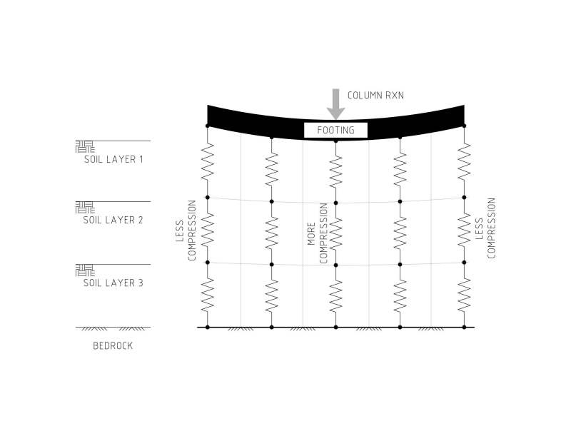
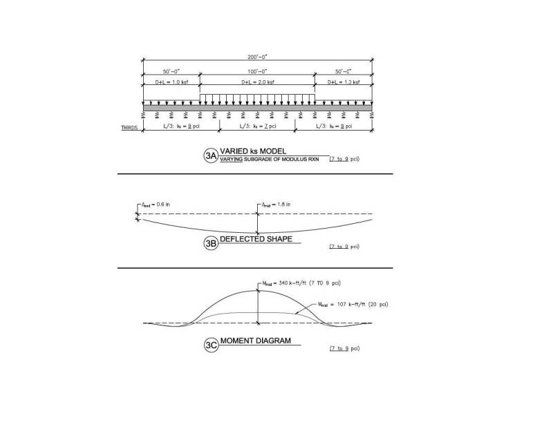
Figure 1 is conceptual. Figure 2 has numbers. Not a small discrepancy; the effect on both thickness and reinforcing is substantial.
This was done in RISA (cracked properties), backfitted to a Plaxis2D run. That is, adjusting the RISA k so the displacement pattern was similar. One iteration. Key input and results are shown. It can easily be checked by anyone. For simple problems, Plaxis is handy with nice color graphs, but not necessary. Hand calcs and influence factor estimations will get you close.
Because an engineer hasn't run thru the numbers on an unfamiliar method does not validate or invalidate the method. If we dismiss an idea or over-simplify, we should have a good engineering basis and some analysis results in hand. Otherwise, we are not unlike our contractor friends who tell us, "I built the last retaining wall half the reinforcing that you said it needed, and it hasn't fallen down yet."
Figure_1_xpw5x9.jpg

Figure_2_ynmaad.jpg
 
ATSE said:
halving or doubling the k of a uniform bed shouldn't change your V & M diagrams more than 10%. If it does, you have a sensitive system that needs more stiffness.

Are you suggesting to never accept a mat stiffness which results in a change in V/M more than 10% unless a more elaborate soil-structural analysis is performed with the geotech?

"It is imperative Cunth doesn't get his hands on those codes."
 
MacG,
I suggest you design large mat foundations that are not sensitive to soil spring variations. You can easily be using a stiffness that is 200% too stiff. For spread ftgs or simple lightly loaded continuous footings, not so much a concern.
Of all the structural parameters structural engineers use for analysis, soil stiffness is the most variable (highest COV), and you have almost control over this, unless you switch to a deep foundation.
Stress influence can reach 2x the building footprint - many times this is deeper than the exploration depths.
If you've seen shear strength plots for concrete, they look like shotgun blasts. Think of the stiffness of a deep clay (varying moisture content, stress history, OCR...) more like a grenade.
 
ATSE – I’m not sure which “last post” you are referring to but I did say that “I suppose in some situations that may be the case”.

A 200 ft. long mat under a 12 story building could certainly be a case where a more precise analysis would be required.

Just to see for myself, though, I took your 200 ft. long mat loading diagram above and analyzed it in RISA. I assumed that your values are for a 1 ft. wide strip of mat – tell me if this is otherwise.

I used your variable soil stiffnesses (7 and 9 pci) and your loads – using Ig for a 1 ft. wide mat strip x 60” deep. (Ig = 216,000 in^4)

Note that the cracking moment for this mat is 285 ft-kips/ft. based on f’c = 4000 psi.

With full Ig for the mat and your 7 and 9 pci stiffnesses I got:
Max Defl = 1.87 inches
Max. M = 245 ft-kips/ft
Max Spring reaction = 24.8 kips/ft (over 12.5 ft)

Note that the mat doesn’t even crack here (245 < 285)

Now If I want to do a parametric analysis and be conservative on my mat I then used 1/2 the values of the soil stiffnesses and re-ran the model.

Max Defl = 3.58 inches
Max. M = 401 ft-kips/ft
Max Spring reaction = 24.4 kips/ft (over 12.5 ft)

Now the mat has cracked.
Using ACI 10.5.4 min. steel I get As min = 0.0018 x 12 x 60 = 1.3 sq. in.
With that the Icr value is 30,098 in^4
With Ms = 401 ft-kips I get Ie = 77,442 in^4

Plugging in this Ie value where the mat is cracked I get the following:
Max Defl = 3.79 inches
Max. M = 191 ft-kips/ft
Max Spring reaction = 24.9 kips/ft (over 12.5 ft)

With 20 pci soil I get even smaller moments (83 ft-kips/ft) and maximum reaction = 25.7 kips/ft.

So with a cracked mat, the moments redistribute throughout the mat and actually reduce the moment. (force follows stiffness).

Based on ACI 318, using a load factor on the moments of 1.6 I get the following:
With full Ig (uncracked) and 7 and 9 pci soil, Mu = 392 ft-kips/ft
As(calculated) = 1.59 sq. in.
As(min 1/3 greater) = 2.11 sq. in.
As(min per 10.5.4) = 1.3 sq. in.
With cracked value for Ie (uncracked) and 7 and 9 pci soil, Mu = 306 ft-kips/ft
As(calculated) = 1.23 sq. in.
As(min 1/3 greater) = 1.64 sq. in.
As(min per 10.5.4) = 1.3 sq. in.

With full Ig (uncracked) and 20 pci soil, Mu = 133 ft-kips/ft
As(calculated) = 0.53 sq. in.
As(min 1/3 greater) = 0.707 sq. in.
As(min per 10.5.4) = 1.3 sq. in.

If we looked at very stiff soil (20 pci) and assumed a cracked mat (which really doesn’t happen) you would still have small moments.

So with all these you have a fairly tight range of required flexural steel in the mat (1.3 sq. in. to 2.11 sq. inches). Technically, per ACI 10.5.4 you only would need the 1.59 sq. in/ft but going conservative at 2.11 sq. in/ft using the 1/3 greater than As(calc) would be my choice here.

I agree with you, however, that the deflections are very sensitive to the soil spring values so for a major building, high-rise, etc. a precise analysis of the soil behavior is required certainly. For most smaller buildings not so much.


Check out Eng-Tips Forum's Policies here:
faq731-376
 
p.s. - I never suggested that the mat doesn't "smile" under load - only that the resulting design doesn't vary that much in terms of concrete/rebar.

The deflections are another matter and I agree that they can be highly variable and sensitive to the soil assumptions.

Check out Eng-Tips Forum's Policies here:
faq731-376
 
MacG, I am in Down Under. For light to medium load say within 200kPa bearing pressure using springs plus some hand calculations for a settlement check may be enough; while if the bearing pressure is say over 500kPa, like a high-rise or over 25m high embankment, even stiff to head clay may become NC then a proper numerical model 2D or ideally 3D seems to be more appropriate.

I am a geotech but have some basic skills on structural design. For soil-structural interaction problems, e.g. Deep excavation/embedded retaining wall,shallow or deep foundations & tunnelling I believe geotech should lead.

I did a 13m high steel water tank design using API 650 before, using SAFE program, it was not sensitive to springs.
 
One last note: Please never use Bowles' formula to calculate spring!

40 x FS x qall (SI units), please do not use! Bowles tells how he derived the formula, it is only for 1 inch = 25mm settlement bearing capacity equations!
 
JAE - nice work. And in short order, no less.
I think we agree far more than we disagree.
In closing, I would make a comparison of results, using your numbers above (my numbers are close to yours).
Max M = 245 ft-kips/ft for the 7pci/9pci spring case
Max M = 83 ft-kips/ft for the 20pci uniform
Many SEs would consider the difference between the two spring stiffnesses inputs a nuance, but there is a 3x factor difference in resulting moments. Or, my experience is that they would not even consider a non-uniform spring value for the mat.
I would argue that if you got M = 83 ft-kips/ft and started your design effort, you would not be specifying a 5 ft thick mat, but instead something like 2.5 ft thick. So the reinforcing comparison, not to mention total concrete, would be more significant, since you would not be include As minimums in the comparison.
 
That's true - but my approach is always to vary the concrete stiffness conversely to the soil stiffness to bracket the design and be conservative.

This conservative approach reflects all the uncertainty of what exactly is the stiffness of the soil. Nailing down the concrete stiffness is rather varied as well but not to the extent of the soil....again for most "typical" moderately sized projects. I think for your 200 ft. mat situation then I'd be all over the geotech to provide me with a more precise analysis of the soil properties.


Check out Eng-Tips Forum's Policies here:
faq731-376
 
Thanks for all of your comments, folks. This thread will be nicely archived in my foundation design files.

"It is imperative Cunth doesn't get his hands on those codes."
 
Status
Not open for further replies.

Part and Inventory Search

Sponsor