Continue to Site

Eng-Tips is the largest engineering community on the Internet

Intelligent Work Forums for Engineering Professionals

  • Congratulations waross on being selected by the Eng-Tips community for having the most helpful posts in the forums last week. Way to Go!

Using a plate for continuous bracing of beam

Status
Not open for further replies.

UnusedHandle

Structural
Dec 18, 2014
13
I work in the crane world and commonly encounter runway girders with long spans. Many times they have deck plate that is attached to the full length of the top flange with stitch welds or bolts at even intervals. There is much debate in my office about how to account for this plate. There is a lot of "engineering judgement" to simply say that the plate provides for continuous reinforcement. However, I would like to quantify the problem. To exaggerate, if the plate were 2 inches thick attached by a continuous fillet weld to a girder spanning 15 feet, then it is simple to say that is is both strong and stiff enough to provide "continuous" bracing to the girder. However, if it were 22ga sheet, spot-welded at 4ft intervals, on a 100 ft simply supported girder, its strength and stiffness are questionable. Where is the line between obviously adequate or inadequate, and how do we quantify it? Appendix 6 of the Steel Manual provides some guidance, but not for continuous lateral bracing. In the past I have just made conservative assumptions, but now I am working on a problem where it could go either way, and the assumption will either make or break the project. Thanks in advance for any thoughts or guidance.

 
Replies continue below

Recommended for you

Kinda depends on how accurate you want to be and how much effort you want to put into the check. A couple of options:

1) treat the plate as eqivalent relative bracing per the AISC appendix.

2) treat the beam and plate as a composite section.


I like to debate structural engineering theory -- a lot. If I challenge you on something, know that I'm doing so because I respect your opinion enough to either change it or adopt it.
 
That really is a judgment call. I would fall back on the "Two Percent Bracing Rule", if the spot-welds or a small group of them, can resist a lateral force equal to 2% of the load on the 100 ft. girder, its probably ok.

BTW, AISC considers the 2% rule to be valid, see this link: AISC Engineering FAQS

[idea]
[r2d2]
 
SRE, the link you provided states that the 2% rule is only for compressive members, but I think that is still the basis for the beam bracing formula since it still has a .02 factor built int. The welds and bolts typically have plenty of strength, my concern is with the plate itself.

KootK, I went with nodal bracing because the plate's other edge is attached to a separate structure. Using Eq (A-6-7) I have a required bracing force of 10.3 kips for my current situation. If this is a 1/4" plate with two bolts every 8inches, what should I use for the equivalent section? The plastic length of the beam is 217 inches, but that doesn't seem right to use that much plate. If I only use a strip of the plate 8inches wide, I would need 5/8" plate to resist the, for L = 48" and K = 1.0 of the plate.

2) If I include the plate in the section properties of the girder, I am limited by AIST Tech. Report 13 to only a small portion of the plate that adds very little to strength and then I eliminate the rest of the plate as a bracing component.

Try not to become a man of success but rather try to become a man of value. - Einstein
 
UH said:
KootK, I went with nodal bracing because the plate's other edge is attached to a separate structure.

Could you sketch a quick plan and section of your situation for us to review? I'm having a hard time visualizing what's going on. This still may well be relative bracing.

UH said:
If this is a 1/4" plate with two bolts every 8inches, what should I use for the equivalent section?

Equivalent section goes out the window if it's truly nodal bracing.

UH said:
If I include the plate in the section properties of the girder, I am limited by AIST Tech. Report 13 to only a small portion of the plate that adds very little to strength and then I eliminate the rest of the plate as a bracing component.

That's another kettle of fish of course. The plate and beam probably act compositely whether you want them too or not. If, per the TR13 stuff, the plate would be locally buckled at full beam capacity, then it may be questionable as to how good of a bracing job it would be doing in that buckled configuration.


I like to debate structural engineering theory -- a lot. If I challenge you on something, know that I'm doing so because I respect your opinion enough to either change it or adopt it.
 
As requested.

While marking this out I noticed that I was wrong about the bolts. It's a single bolt every 8", for the difference that makes.

Kootk, you will probably have to elaborate on why I couldn't use an equivalent section for nodal bracing.

The plate and beam composite action is part of the concern. TR 13 allows us to include a small part of the plate as part of the vertical section properties and a larger portion for the horizontal properties. If the girder has a lateral load at the top flange between supports, the plate will definitely carry some part of that load, but what I've seen occur is that some engineers use the plate to add far more to the lateral strength than I think is appropriate.

If we assume continuously braced, then that means the girder can develop its plastic moment without that plate failing, which I find unlikely, agreeing with your third point, and which is my argument against some of the assumptions I've seen.

Short of FEA, I don't know a good way to determine the amount of stress that plate will be subjected to from the loadings in two directions.

My thought right now is to settle on ignoring the plates contribution to the vertical section properties of the girder, include the allowed portion per TR 13 for lateral, and use the tie-back locations for unbraced length. That would be 25' per the sketch.

Try not to become a man of success but rather try to become a man of value. - Einstein
 
 http://files.engineering.com/getfile.aspx?folder=23bfec5d-8c2a-47c3-8e89-2a17f1c7b18f&file=Braced_Girder.pdf
You could still use an equivalent section if it's bolted to the beam at X distance on center, you will just need to check shear flow between the plate and the beam and make sure the bolts can resist the shear flow between the two sections.
 
UH said:
As requested.

Killer sketches. Thanks.

UH said:
Kootk, you will probably have to elaborate on why I couldn't use an equivalent section for nodal bracing.

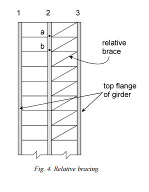
You can use an equivalent section with relative bracing because the bracing flexes along with the braced member. Like a horizontal truss or beam in its own right. With nodal bracing, each brace is considered stationary at the far end, making it tough/impossible to represent it as an equivalent stiffness flexural member. It won't matter here anyhow; you've definitely got relative bracing.

UH said:
If we assume continuously braced...

You've absolutely got continuous bracing. Better than that; taken together with the truss and the lacing, you have a full on three dimensional truss. "Okay by inspection" with regard to LTB.


I like to debate structural engineering theory -- a lot. If I challenge you on something, know that I'm doing so because I respect your opinion enough to either change it or adopt it.
 
Check out this paper by Yura: Link. Clip below. You should be able to glean some solid ideas from that.

Capture1_mtrrzy.png


I like to debate structural engineering theory -- a lot. If I challenge you on something, know that I'm doing so because I respect your opinion enough to either change it or adopt it.
 
Status
Not open for further replies.

Part and Inventory Search

Sponsor