Eng-Tips is the largest engineering community on the Internet

Intelligent Work Forums for Engineering Professionals

  • Congratulations waross on being selected by the Tek-Tips community for having the most helpful posts in the forums last week. Way to Go!

Using CAD to help with Aircraft Conceptual Design 1

Status
Not open for further replies.

WK95

Mechanical
Dec 20, 2013
54
0
0
US
I am working on a aircraft conceptual design project and am at the stage where I need to work on the layout and configuration design of the aircraft. To help out with this, I'm been using CATIA however probably not as well as it should be used.

Note that because I am only in the conceptual design stage, I am mostly just concerned with developing the general shape of the aircraft, the general configuration of that various components, and the approximate dimensions.

1) Best way to model fuselages, wings, and other components?
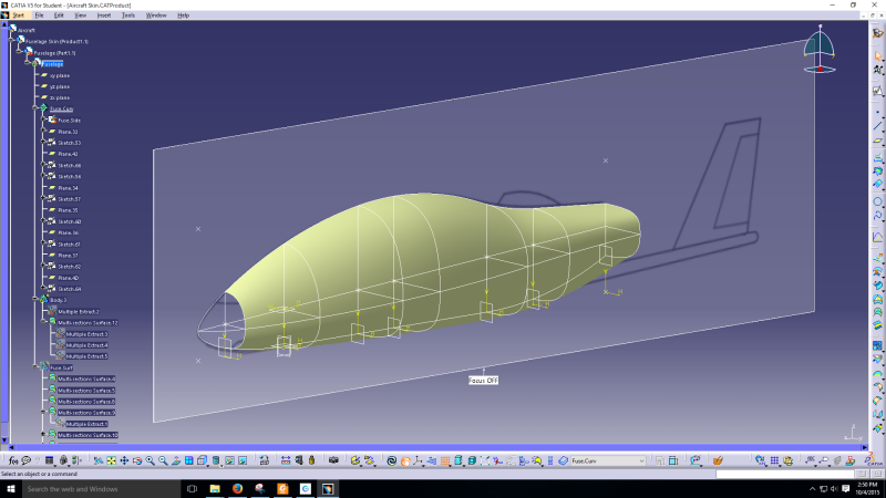
How I make a fuselage is to create a side view sketch of the fuselage, a top view, then cross sections. Using these, I can make a a surface using those sketches as guide curves in the Generate Shape Design workbench. To modify the shape as necessary, I just go into the sketches and modify their shape and because I make the sketches associative, adjustments in the top and side view sketches will adjust the cross curve sketches.
Screenshot_5_f897cv.png


Is this is good way to go about modelling a fuselage or can it be done better?

In the future, when I get to the stage where I have to do work on laying out the structure, for a component like a wing, I would use the surface to create a boundary for the aircraft skin and internal structures such as ribs and spars.

Things get a bit tricky then because my aircraft design will be of composite construction, likely foam core and fiberglass. I also ran into some trouble making the surfaces since after making the sketches, when I mirrored them to the other side then tried to make a surface covering the entire fuselage, I run into various messy errors. I ended up needing to just make half a surface then mirror it.


2) Work with parameters?

In an excel document, I have spreadsheets where I do all my calculations to estimate things like wing span and mean chord length. I then manually transfer these values into CATIA by setting up parameters. I then make a sketch of a wing in the top view and dimension them using the parameters and some very simply formulas.

Is it possible to link Excel and CATIA such that changes in values in Excel are reflected in CATIA?

3) Organizing products, components and parts

To start, I make a Product file in which I create other Products, Components, and Parts. Here is the general organization

-ConceptPlane
--Fuse.Surface (Product)
---Fuse.Sketch (Part)
----Here goes the top, side, and cross curve sketches
---Fuse.Surface (Part)
----Surfaces are made here using Generative Shape Design workbench.
--Wing.Surface (Product)
---Wing.Sketch (Part)
----Here goes a top view sketch of the wing planform.
---Wing.Surface (Part)
----Surfaces are made here using Generative Shape Design workbench.
And so on.

Is this a good way to organize the components or can it be done better?
 
Replies continue below

Recommended for you

etude-conception-issoire-aviation-1421_ampknd.jpg


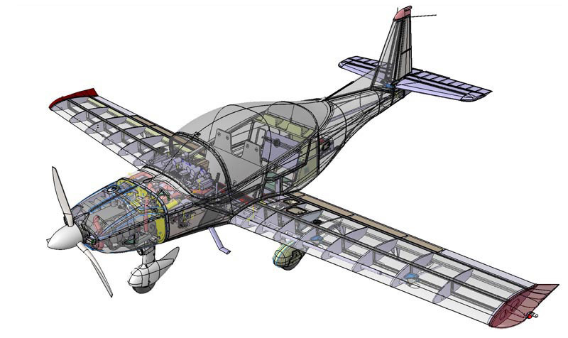
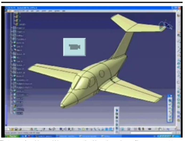
Mostly, I want to learn how such a design like this is made using CATIA from start to finish. Now, I know that the entire process takes many many manhours but I'd appreciate if someone could offer some insight as to the process for making such a model.
 
What are you doing all this work for? If you plan to make a real aircraft from your design, make sure to plan for at least 1000 hours to get your CATIA model 90% done. The last 10% will take about 2000 hours to finish.

The second graphic you posted (Piper Cherokee?) would make a good Jane's All The World's Aircraft illustration, but it's nowhere near detailed enough to inform the actual fabrication of any parts. What level of detail is your target?

You can set up a "pivot table" that allows an external file to drive parameters in any parametric 3D model. I don't speak in CATIA, but I've done it in many others.

Somehow, it looks like you are making part models all in the same part file. Real aircraft are assemblies of thousands of parts. Structuring the model as an assembly of many sub-assemblies of many parts is good practice. Adopt a plan for your assembly "tree" before you start sketching.

Consider creating master parts that are not actual parts but lofts of surfaces and/or sketches of very basic geometric lines, from which you will derive the actual parts. Use these models as references to be inserted into part models as applicable. Let them provide the external geometry, by reference, and let the individual part files have the little details like laminate thicknesses, bolt holes, etc.


STF
 
There are other forums that you should post any CATIA related questions in.

As for using CAD to do conceptual design of an aircraft, you typically start by defining the aircraft OML surfaces. Constructing the OML surfaces using parametric geometry makes it easy to modify the model. But things can get ugly quickly with linked and parameterized models if they are not constructed carefully.
 
This is strictly a personal design effort carried out primarily as a learning experience. As for the level of detail, I am only in the conceptual stage of aircraft design. I am not yet working out the exact dimensions of all the parts and the locations of the rivets to anything like that. In the future, if I feel the concept is feasible and the design study yields good results, I do plan on then doing detail design with the end goal of developing a prototype homebuilt experimental airplane.

Andyep, I've been trying to structure my work. I'm using a top down design approach where I first make the external geometry I.e. the skin and use that to constrain the dimensions of other components. Fuselage and wing surfacing, for example, are done as different Products within a product file. This was one of the first things I learned for assembly work and top down design and it has shown to be immensely useful.
 
Tbuelna, do you have any links to any websites or resources that go into detail about how to make OML surfaces properly?

Also, on a Google search for CATIA Outer Mold Lines, the results are mostly relating to CATIA's sheet metal capabilities. Will OMLs be useful to me if I'm designing my aircraft to have a composite construction? I plan to use foam core and fiberglass.
 
GregLocock, its the same with aircraft. Spreadsheets or stuff like Matlab are used to do the math first. For example, I have a spreadsheet setup to handle preliminary sizing to estimate wing area, span, mean chord length, landing gear size, weight, etc. WNow, I'm using CATIA for the layout work to determine the approximate locations of various components. Where possible I use parameters to define geometry as is the case for the wing planforn sketch.

I just need to figure out a way to connect Excel and CATIA. Besides that, my primary concern right now is the process of making a plane in CATIA and the methodology pertaining to using CAD to help with conceptual design. This is tricky since there is very little information about it online. I imagine this sort of thing tends to be kept within company doors.
 
work with parameters ? the wing (and h.stab) can be parameterised as you're thinking. Decide on a airfoil section, then you can start to make surfaces of the wing. maybe make a tip section and a root section and taper between (the tip airfoil is often quite different to the root. better would be if you can project a scaled airfoil from the root datum along an axis (not necessarily normal, so you can include sweep), better again if you can rotate this section (for twist, wash-out). the olde school approach would have been to create a set of points on the airfoil and manipulate these, mathematically ... copy the root airfoil out along the span, scale the section a/r, twist the section a/r, sweep the section a/r.

making the fuselage from sections ... I see no other way. set up the various sections along the fuselage axis; round continuous stringers (lines) over them to give a smooth external surface, build the surface from these lines.

another day in paradise, or is paradise one day closer ?
 
WK95 said:
Tbuelna, do you have any links to any websites or resources that go into detail about how to make OML surfaces properly? Also, on a Google search for CATIA Outer Mold Lines, the results are mostly relating to CATIA's sheet metal capabilities. Will OMLs be useful to me if I'm designing my aircraft to have a composite construction? I plan to use foam core and fiberglass

The OML is a geometric definition of the aircraft's outer surfaces. To generate a 3D digital model of the aircraft OML the surfacing tools in CATIA work quite nicely. The approach you are using to model your fuselage OML looks OK. As rb1957 noted, for wings and control surfaces you will typically start by importing and linking tables of 2D airfoil point sets that were exported from some other aero design application. Then you construct a smooth 2D sketch curve from each airfoil point set, position each 2D airfoil sketch along the span with the correct sweep/scale/twist/tilt/etc, and then construct a smooth surface along the 2D curves. This last part is not easy. Modeling a surface with the accuracy and smoothness required for an aircraft wing or control surface takes a significant level of skill, and this only comes from lots of experience.

Once you have a complete OML surface definition, you can export the surfaces (hopefully with links) to other applications for analysis or further design work. The OML master surfaces are the basis for designing many composite structures and tooling. It is extremely helpful if you can create a link between the CATIA model file and the file created in the other application. This way any changes made to the CATIA model can be pushed thru to the linked model and updated, hopefully without too much grief.
 
I said the approach you are using to model your fuselage OML surface looks OK. However, I can't tell whether your actual surfaces are satisfactory for your application. Most surfaces look nice when viewed at a distance, but don't look so great upon closer inspection. CATIA has some sophisticated surface analysis tools that you can use to check your surface quality. Definitely worth using if you have access to them. Check for continuity and smoothness of individual surface sections, and smooth transitions with no gaps at each surface boundary. If you are going to use the surfaces for creating FE meshes, do a test run to make sure there are no degenerate elements, gaps between surface boundaries, or small patches of surface that won't mesh cleanly.
 
hello,

some quick thoughts:
1. at the START of the Conceptual design, there's not fixed OML, yet.. The engine location, even number of engines, is under investigation, depending on their trade-offs against performance requirements.

2. This means, there will be several CAD models, representing the alternatives, some alternatives will also include child-alternatives (alternative 2a, 2b, 2c, etc.).

3. The example of 13 OCT, 23:48 post, is not the end of a conceptual design, it's a preliminary design including the components, equipment locations. Aircraft Conceptual Design, most of the time does talk about the general layout of the aircraft (MTOW, Fuel Fraction, landing gear arrangement, tail configuration, number or location of engines, general bays (payload bays, seating arrangements,) etc).

4. composite or metal, CAD will facilitate "reusing" and "developing/changing" designs. A Product tree would help enormously, especially during preliminary design (where you are assigning functions to systems, and trying to find out how many parts/equipment those systems will employ).

5. It is a great, challenging task to design a complete aircraft, on cad, with several hundred components. And your open approach to asking to understand the process (using CAD) is much appreciated.

6. Good luck. :)
 
Hi gurkanc,

1) I know the OML isn't fixed yet so I made the sketches and surfaces in a manner that adjustments can easily be made to the OMLs and the surfaces will update accordingly. It'll probably get fixed once I get everything to fit inside the fuselage and refine the aerodynamics of the shape.

2) I haven't used CAD to model multiple configurations since I'm trying to figure out how to even model just one in the first place. However, I've made sketches to look at the various configurations many of which are attractive and feasible in their own right. Ultimately though, I've settled with a configuration that I find meets my needs in an airplane best.

3) Some books I have such as Raymer's conceptual design book describes the stages of design as conceptual, preliminary, and then detail design. Roskam's series of design books just has preliminary and then detail design. In that manner, it just seems there is no concrete boundaries between design stages especially since in the real world, a lot of the stages are blended together in some manner.

4) CAD/CAE will especially be helpful with with the structural design component especially because FEA can help with composite designs. I'll try to fiddle with that once I take some more of the requisite courses at my university.

5) Yep. Mostly I'm going about this project because I traditionally universities don't do much to actually teach engineering design asides from a senior year design project. This project is a good way to start applying some of the concepts I learn in school which is especially the case when I get to the structural design phase (That's the part I'm most looking forward to). And of course, designing an entire aircraft even a homebuilt category one takes many years but the good stuff never does come easy but it's certainly been done by various dedicated individuals.

6) Thanks!
 
It's never too early to make estimates of all portions of a design, particularly for an airplane.

Set up some requirements for empty weight, payload, flight speed, power, and fuel/duration. Once these are in place the general arrangement can be worked out and estimates made for CG, landing gear, and stability. Estimate the span and A/R to get an idea of the induced drag.

I'd recommend a 1/4 scale R/C model to verify the estimates. In many planes it isn't the ability to fly that is of interest but whether it handles well and recovers from upset well; both are characteristics that can be difficult to calculate.
 
3DDave,

I already have estimates for empty weight, payload, cruise speed, and endurance so most of the preliminary sizing work has been done. I haven't gotten to the stability and weight and balance portions though.

Also, an RC model is a great idea but there is an inherent difficulty with scaling things down be it for wind tunnels or RC models especially because the RC model will operate at a much lower reynolds number than the full size plane which I'm wanting to cruise at 170kts.

I like the BD-5 but its not quite the airplane I'm looking to design. Mine carries 4 persons.
 
WK95- CATIA V5 is an extremely powerful design tool. The system of parameters, constraints, links, relationships, formulas, etc. that you create in one model or from model-to-model can be your best friend or your worst nightmare. So you need to carefully consider every parameter, link, etc. that you create, and the full impact it will have when you need to modify it. For example, if you intend to evaluate several different OML shapes and at some later point swap out one OML shape for another at the next part/product level, make sure you use consistent naming for any features that will be linked at the next level. This will allow the model to recognize related features after changing the linked file.

Another thing that might be helpful would be to create a master skeleton file consisting of points, lines/axes, planes, coordinate systems (BL,WL,STA) defining location of basic features on the aircraft. This skeleton file can be linked and used as a common basis for different OML surface models.
 
Status
Not open for further replies.
Back
Top