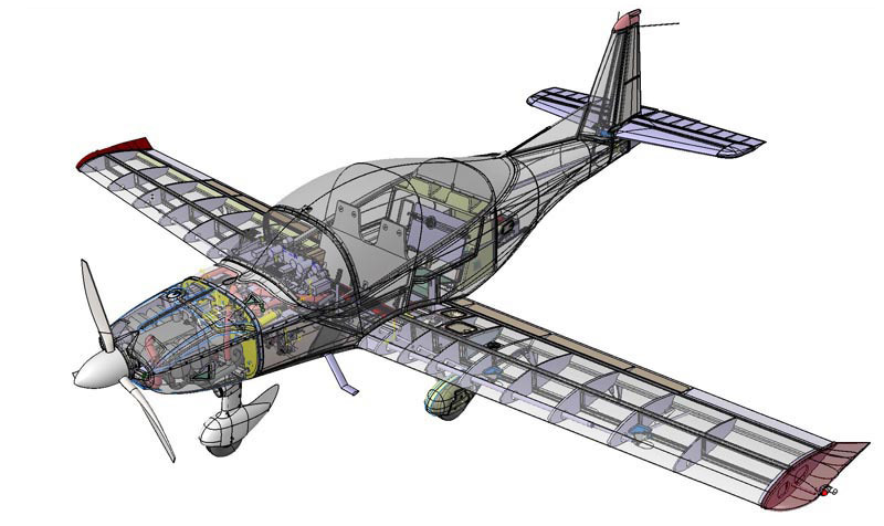
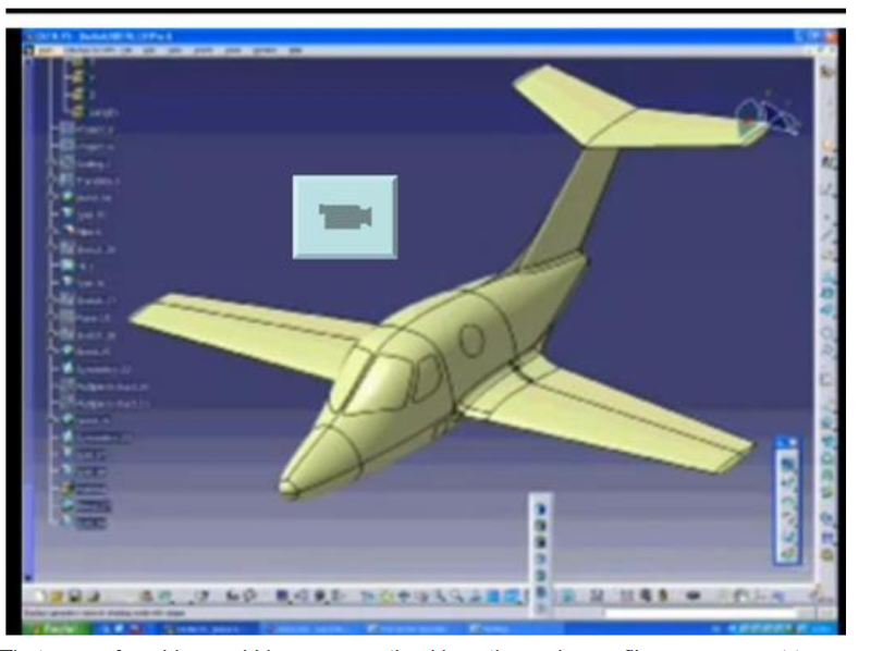
I am working on a aircraft conceptual design project and am at the stage where I need to work on the layout and configuration design of the aircraft. To help out with this, I'm been using CATIA however probably not as well as it should be used.
Note that because I am only in the conceptual design stage, I am mostly just concerned with developing the general shape of the aircraft, the general configuration of that various components, and the approximate dimensions.
1) Best way to model fuselages, wings, and other components?
How I make a fuselage is to create a side view sketch of the fuselage, a top view, then cross sections. Using these, I can make a a surface using those sketches as guide curves in the Generate Shape Design workbench. To modify the shape as necessary, I just go into the sketches and modify their shape and because I make the sketches associative, adjustments in the top and side view sketches will adjust the cross curve sketches.
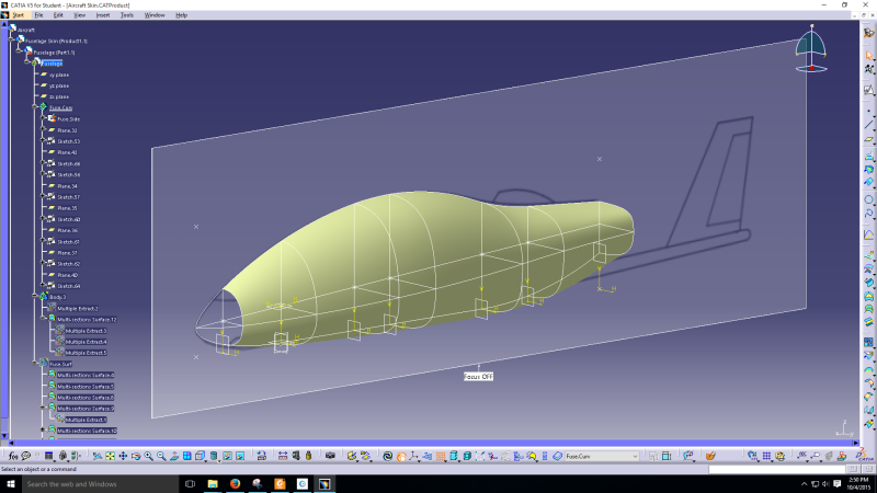
Is this is good way to go about modelling a fuselage or can it be done better?
In the future, when I get to the stage where I have to do work on laying out the structure, for a component like a wing, I would use the surface to create a boundary for the aircraft skin and internal structures such as ribs and spars.
Things get a bit tricky then because my aircraft design will be of composite construction, likely foam core and fiberglass. I also ran into some trouble making the surfaces since after making the sketches, when I mirrored them to the other side then tried to make a surface covering the entire fuselage, I run into various messy errors. I ended up needing to just make half a surface then mirror it.
2) Work with parameters?
In an excel document, I have spreadsheets where I do all my calculations to estimate things like wing span and mean chord length. I then manually transfer these values into CATIA by setting up parameters. I then make a sketch of a wing in the top view and dimension them using the parameters and some very simply formulas.
Is it possible to link Excel and CATIA such that changes in values in Excel are reflected in CATIA?
3) Organizing products, components and parts
To start, I make a Product file in which I create other Products, Components, and Parts. Here is the general organization
-ConceptPlane
--Fuse.Surface (Product)
---Fuse.Sketch (Part)
----Here goes the top, side, and cross curve sketches
---Fuse.Surface (Part)
----Surfaces are made here using Generative Shape Design workbench.
--Wing.Surface (Product)
---Wing.Sketch (Part)
----Here goes a top view sketch of the wing planform.
---Wing.Surface (Part)
----Surfaces are made here using Generative Shape Design workbench.
And so on.
Is this a good way to organize the components or can it be done better?
Note that because I am only in the conceptual design stage, I am mostly just concerned with developing the general shape of the aircraft, the general configuration of that various components, and the approximate dimensions.
1) Best way to model fuselages, wings, and other components?
How I make a fuselage is to create a side view sketch of the fuselage, a top view, then cross sections. Using these, I can make a a surface using those sketches as guide curves in the Generate Shape Design workbench. To modify the shape as necessary, I just go into the sketches and modify their shape and because I make the sketches associative, adjustments in the top and side view sketches will adjust the cross curve sketches.
Is this is good way to go about modelling a fuselage or can it be done better?
In the future, when I get to the stage where I have to do work on laying out the structure, for a component like a wing, I would use the surface to create a boundary for the aircraft skin and internal structures such as ribs and spars.
Things get a bit tricky then because my aircraft design will be of composite construction, likely foam core and fiberglass. I also ran into some trouble making the surfaces since after making the sketches, when I mirrored them to the other side then tried to make a surface covering the entire fuselage, I run into various messy errors. I ended up needing to just make half a surface then mirror it.
2) Work with parameters?
In an excel document, I have spreadsheets where I do all my calculations to estimate things like wing span and mean chord length. I then manually transfer these values into CATIA by setting up parameters. I then make a sketch of a wing in the top view and dimension them using the parameters and some very simply formulas.
Is it possible to link Excel and CATIA such that changes in values in Excel are reflected in CATIA?
3) Organizing products, components and parts
To start, I make a Product file in which I create other Products, Components, and Parts. Here is the general organization
-ConceptPlane
--Fuse.Surface (Product)
---Fuse.Sketch (Part)
----Here goes the top, side, and cross curve sketches
---Fuse.Surface (Part)
----Surfaces are made here using Generative Shape Design workbench.
--Wing.Surface (Product)
---Wing.Sketch (Part)
----Here goes a top view sketch of the wing planform.
---Wing.Surface (Part)
----Surfaces are made here using Generative Shape Design workbench.
And so on.
Is this a good way to organize the components or can it be done better?
")