Eng-Tips is the largest engineering community on the Internet

Intelligent Work Forums for Engineering Professionals

Using Thermocouple Feed-Thru Spare Terminations for Drain Wire

Status
Not open for further replies.

centaur21

Electrical
Jun 5, 2006
44
0
0
US
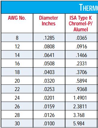
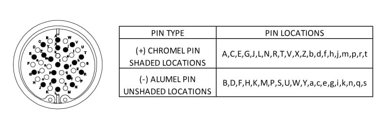
I have a 41-pin thermocouple (type K) feed-thru flange for connecting a multipair thermocouple extension cable from within a vessel to the outside. The multipair cable has an overall shield and drain wire. I have 5 spare pins on the feed-thru flange; 3 are chromel (+) and 2 are aluminel (-). I want to use one of the spare pins to bring my drain wire across. I don't have any other way except the feed-thru flange for bringing the drain wire across. There's potential for noise and would like to use the drain wire for this purpose. Do you see any issues with this? Please provide feedback.

41-PIN_TC_Feed-Thru_Flange_oklgq3.jpg

Thank you!
 
Replies continue below

Recommended for you

Is the connector shell inside isolated from the one outside?
What noise are you worried about that your instrumentation is not set up to filter?
Any temperature instruments that I recall would reject any signals above a few Hz.

= = = = = = = = = = = = = = = = = = = =
P.E. Metallurgy, consulting work welcomed
 
The process is induction melting of a specific metal. Thermocouples are used for measuring the temperature of the container holding the molten metal. A type K extension cable ties the thermocouples to the feed-thru 41-pin flange. Another multipair cable is connected to the exterior vessel side of the flange where it then ties to a PLC.
 
T/C alloys are much higher resistance the copper wire, so the use of any appreciable length of the T/C cable to get to a ground connection will have some wiring resistance. Bear in mind that the table is Ohms per double feet (out and back).

Ohms_per_double_foot_Type_K_h9tgfi.jpg
 
Using Ks, I hope that is low temp work.
Type K drift like mad.
We never use them above 1500F, we switch to N.
I don't see what the problem is.
Simply connect the shield through the flange, but first check to see if it is grounded.
If so then leaving it isolated may be better to avoid ground loop issues.
Besides in induction melting you will need to momentarily cut power to get a real temperature reading.
It is the only way to make it work.
It is also what people spend big money on optical pyrometers.

= = = = = = = = = = = = = = = = = = = =
P.E. Metallurgy, consulting work welcomed
 
I agree with you EdStainless about the optical pyrometers but we are building a prototype that will be tested, tweaked, etc., and potentially go into production once they get it where they want it or how they want it, cost is has a big part in the equipment we're choosing.
The process temp will be around 1100°C and I'm looking to switch to type N. I'm taking the place of another engineer and this is the information that was handed to me so I'm trying to clean it up and make the necessary changes as I go through the data.

Thanks guys. I greatly appreciate your feedback!!
 
IR may not be as expensive as you think.
We vac melted and used a simple single wavelength pyrometer.
We only melted a small group of very similar alloys.
And we only really cared about the casting temp and not so much intermediates.
We did tests using Pt TC for ref and then selected an emissivity that gave us the right temp reading.
It was a very simple and robust system.
If there is smoke or fumes, or if you will work with many different alloys then a ratio pyrometer would likely be a better option.

= = = = = = = = = = = = = = = = = = = =
P.E. Metallurgy, consulting work welcomed
 
Status
Not open for further replies.
Back
Top