Continue to Site

Eng-Tips is the largest engineering community on the Internet

Intelligent Work Forums for Engineering Professionals

  • Congratulations SDETERS on being selected by the Eng-Tips community for having the most helpful posts in the forums last week. Way to Go!

V-Belt Wear

Christo_AU

Structural
Sep 4, 2023
20
Good day

I am not very experienced with the design of powertrain parts and would appreciate any help.

I have designed a v-belt and pulley assembly, please see the picture below. The load (platform lifted with screws) is normally driven by a servo motor. In case of a power failure, the platform can be lowered with a hand crank or hand drill connected to a 1/2 inch socket. The socket is on one end of the pulley assembly. So the pulley assembly will normally not be transmitting any power, but will always run (no clutch). This system will only run for 5 minutes, twice a day, 5 days per week. Service life is 10 years, so total is about 217 hours.

A fitter is concerned that the v-belt will wear out pretty quickly. I asked why but he didnt provide details, other than "sh** design". I assume it might be becuase the idler/tensioners push on the back of the v-belt. Note the v-belt is cogged.

Will this v-belt last for 200 hours of operation at 1630 RPM over 10 years? If not, any guesses as to how long it might last?

Thank you in advance.
Christo
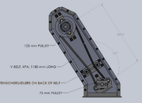
1743126175540.png
 
Replies continue below

Recommended for you

Belt makers often have tech support to help with such questions. I think it may age out but I doubt it will wear out. Belt drives can suffer significant damage and keep on turning.
 
Thanks Dave, thats a relief.

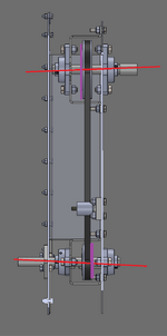
I have since also spoken to my boss. Although he isn't too concerned, he did mention that if the two shafts aren't parallell (red lines), the pulleys could wear out the belt. This could also happen if the pulleys aren't on the same level (purple lines). I think this might have happened, it does feel rather dificult to turn by hand. Below is a picture from the side:

1743129708253.png
 
V-belts are high friction devices. If it is to be easy to turn use flat belt with pulley guides or micro-V belt.

None are especially tolerant of non-parallel shafts, but the maker tech engineers will have some guidance on how much there can be without causing a problem.

If you change the computation from hours to cycles and compare to automotive use cycles, I think you will see that this is really light duty.

Figure the belt speed/belt length to calculate cycles.
 
Thanks Dave, thats a relief.

I have since also spoken to my boss. Although he isn't too concerned, he did mention that if the two shafts aren't parallell (red lines), the pulleys could wear out the belt. This could also happen if the pulleys aren't on the same level (purple lines). I think this might have happened, it does feel rather dificult to turn by hand. Below is a picture from the side:

View attachment 7312
From the limited view.
Summarize please explain how the bearings are held aligned. All I see it is bolted to sheet metal. How is it held precise.
It's important hold fixed alignment.
I would also change the belt configuration.
And the pulley design.

Look at how some automobile designs on precisely mounted shafts and bearings
And very right. Thin sheet metal may have
Excessive vibration. Remove the two idlers.
Add one idler with spring tension.
The only solution I see here is to match drill
And bore two holes to mount component with bearings at each end. Make the bolt holes loose for bolt clearence.
 
Hi Dave

Thank you, I calculated the cycles and its about 10% of an auto's v-belt cycles before replacement, also at no load. The assembly has since been readjusted and its much easier to turn now, I measure it at about 0.6 Nm. It should all be okay.

Hi mfgenggear

Thank you for the great suggestions. Yes you are correct, the bearings on the right are only held by the sheetmetal housing, while the bearings on the left are held by thin sheetmetal brackets, bolted to the housing. I thought that the fitters could align these, but I realise now that this is a bad design. As stated before, I am unexperienced in design of power transmisison parts. Unfortunately it's too late to change the configuration now, it has been built already. But I think it will be okay (The assembly has since been readjusted and its much easier to turn now)

PS I added two idlers because it will be driven in both directions, so the slack side will alternate. Not sure if this is actually required?
thank you, but it can still be reinforced
with .125 square cut stiffening plates
riveted in place with a machine hole.
have them use precision level to align it.
then use mag base indicator stands
to final verify runout
than match drill for rivets. hopefully will help
distribute or dampen the vibration.
old aircraft trick.
any way a suggestion.
good luck.
 

Part and Inventory Search

Sponsor