Continue to Site

Eng-Tips is the largest engineering community on the Internet

Intelligent Work Forums for Engineering Professionals

  • Congratulations KootK on being selected by the Eng-Tips community for having the most helpful posts in the forums last week. Way to Go!

Variable frequency drive with different power sources 3

Status
Not open for further replies.

John_Hoekstra

Structural
Oct 8, 2017
8
Good day people

I have a question about a Variable frequency drive and I hope somebody could help me with it. In my free time, I try to get more knowledge about electric drives. I stumbled on a question that I couldn't find directly an answer on it. The question is: Do you need a buck converter after your inverter if you have different source voltages? For example, you have a mobile unit and you want to be able to make it available for 690 400, etc.
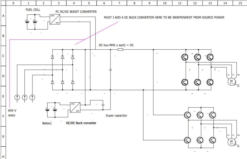
TEST-XXX3_iajp9p.jpg


Thanking you in Advance

With regards,

John
 
Replies continue below

Recommended for you

Dear itsmoked

Thank you for your fair remark. It was late I mixed up the letters of the abbreviation. I have corrected it.

With Regards,

John
 
Ah. OK. Thanks.

If you feed any particular VFD at the DC bus then you can feed it via a DC-DC or in fact anything that can keep up and that will never exceed any included bleed (voltage limiting) (energy diverting) sub systems. You can never exceed the allowable DC bus voltage without likely causing damage that can be very energetic. (Very, very, energetic)


Using the term "after the inverter" as you have is also confusing as the entire drive was usually refereed to as the "inverter" early-on, but that poorly descriptive terminology has been superseded by VSD or VFD.

Perhaps you meant "after the rectifier stage"?

No matter what one decided to do they certainly can NOT exceed the output stage design with whatever they put into the AC line inputs or via the DC bus input. You cannot feed a VFD a higher voltage just because you'd like to.

One might be able to follow for example a 230V output drive with a 230V to 460V transformer to drive a 460V motor. Though that would be expensive, painfully heavy, and asking for problems of several types. Not advised and not needed as one can typically re-tap the motor to the lower voltage.


Keith Cress
kcress -
 
Itsmoked said:
One might be able to follow for example a 230V output drive with a 230V to 460V transformer to drive a 460V motor. Though that would be expensive, painfully heavy, and asking for problems of several types. Not advised and not needed as one can typically re-tap the motor to the lower voltage.
Hi Keith.
There are a couple of interesting exceptions.
SAGD bitumen extraction.
This is often done with Down hole submersible pumps that will have very long motor leads.
1000 Feet to the motor is not unreasonable.
The pumps are often 4000 Volt rated.
The voltage spikes must be mitigated.
Two choices, an expensive 4160 Volt VFD and 4160 Volt filter,
or
A 480 Volt or 600 Volt VFD and harmonic mitigation by a transformer stepping up to 4160 Volts.
I did some work on a SAGD pad.
The wells are laid out wagon wheel fashion from a central pad.
All of the wells used 4000 Volt submersible pumps.
About half of the wells used a 4160V VFD and a filter.
The other wells used a 480 Volt VFD and a 480:4160 Volt transformer.
Another possible exception;
I have heard rumours that some compressor skid manufacturers were doubling the HP of the motors by running 230V, 60 Hz, 1800 RPM motors at 480V, 120hz, 3600 RPM.
This has an added advantage for high speed centrifugal compressors; your gearing to the high speed impellers will be a lower ratio.
If you were to relocate one of these to a location with only 240 Volts available, then a transformer may be a cost effective solution.
These are two oddball exceptions to Itsmoked's comments.
Itsmoked's comments are accurate in the majority of cases.

Feeding the DC bus from different sources:
The bus will draw current from whichever source has the higher voltage.
Source impedances and ripple currents may complicate this somewhat.

Bill
--------------------
Ohm's law
Not just a good idea;
It's the LAW!
 
Yes, in sub pumps we prefered 480 VFD and transformers. In a single motor size we could could build motors for 825V, 1115V, or 2185V. And then people would stack 2 or 3 motors, and give cable losses of 50-600V (14,000' extension cord) and you can see the jigsaw puzzle of selecting voltages.
And the transformers were usually multi tap so that we could go +/-100V as needed in the field.
Except for small motors 1500-5000V was the range that we aimed for.

= = = = = = = = = = = = = = = = = = = =
P.E. Metallurgy, consulting work welcomed
 
Clear Itsmoke/ Waross

It was late and indeed it was a rectifier. It is indeed not the intention to bring the DC bus to a higher voltage, but the intention was to bring the input voltage down to the output voltage. It is for a mobile unit that can be placed anywhere in the world and also on ships. Unfortunately, the voltage is not the same everywhere.

If I understand you correctly for a double-check.

Suppose I have one which a system that is designed for a 400V/AC 50Hz or 400 x srqrt2 = 560 Volt/DC. The input voltage is then 690V/AC, then the best thing to do is to transform my input AC voltage with an auto-transformer? The auto-transformer will transform the voltage to 400VAC available to my rectifier. This method is the most efficient way to get my voltage down.

The option to use a buck converter after the rectifier is not possible, because
1 the rectifier is usable for a specific voltage range
2 Expensive

Thanks for your answer and the time you want to help me.

 
Use a VFD suitable for the highest voltage expected.
Use and program the motor for the lowest voltage expected.

Bill
--------------------
Ohm's law
Not just a good idea;
It's the LAW!
 
waross said:
Use a VFD suitable for the highest voltage expected.
Use and program the motor for the lowest voltage expected.
Within limits, most VFDs have limits to how low the incoming AC voltage can be, for example I know of several that will allow no lower than -15% on the input. So if you use their 690V drive, it will give an Under Voltage fault on even a 480V input, let alone 400V. The best I have seen is 430V minimum for a 690V drive. I have done this with 480V drives that can accept down to 380VAC input and stay running, but I have never looked for this kind of range. For a 690V drive to accept 400V, it would have to allow at LEAST -42%, and that leaves no room for variance at the 400 level, i.e. they REALLY have 380V and it is -5%, so call it an allowable -48% input voltage tolerance. Good luck with that. Most likely you are going to have to work with a VFD manufacturer who can customize their drive, or one that sells a Common DC Bus system with a highly flexible line converter section.

Then there is the motor side to consider. If you have to accommodate an option for a 400V input, that would require using a 400V motor. That then means if you move to a location with 690V as the input to the drive, that motor is getting PWM pulses that are based on an 970VDC bus, instead of a 540VDC bus. That's going to stress those windings and they will prematurely fail if not accounted for in the motor design. So make sure the motor supplier is aware of this and uses magnet wire rated for 2,000V or more.

As to the issues in the original posting, you CAN connect different DC busses to a VFD, but you MUST make sure to remember that they would all need their own pre-charge circuits, or use a VFD that has a DC bus with it's own pre-charge circuit built-in that you can tap into AHEAD of that. Some do, most do not. You would also want separate fusing of each DC source.


" We are all here on earth to help others; what on earth the others are here for I don't know." -- W. H. Auden
 
To resolve the limits on input voltage Jraef points out, it is possible - but expensive - to order a drive with custom drive program from some OEM's. Electric Locomotive traction drives routinely handle a very wide (+/- 20% per IEC 60850) input voltage range.

It is possible for a drive technology to accept a large range of input voltages, but for constant power as the input voltage goes down the amps go up, so the input side must be designed for both the highest voltage, and the highest amps.

A custom transformer that can be tapped for all of the likely input voltages at 50 Hz and 60 Hz while staying inside the +/- voltage limits for a standard drive, could be used in place of a custom drive program. This may be the easier solution, as adjusting transformer taps is simpler to explain to electricians than drive programing. For a worldwide mobile application, it is important to keep the field setup requirements simple, as they may need to be explained through a language gap.

 
Status
Not open for further replies.

Part and Inventory Search

Sponsor