Eng-Tips is the largest engineering community on the Internet

Intelligent Work Forums for Engineering Professionals

  • Congratulations waross on being selected by the Tek-Tips community for having the most helpful posts in the forums last week. Way to Go!

variable intake / independent throttle body idea

Status
Not open for further replies.

timiacobucci

Automotive
Aug 24, 2014
19
0
0
US
I recently had an idea for a modification of an independent throttle body system to mimic the function of a variable geometry intake system simply using throttle opening.

Until recently I had not considered that part of the responsiveness of an itb system lies in the port velocity generated at part throttle opening. Aside from the possibly more turbulent airflow around the butterfly vs a specifically engineered multi runner variable geometry manifold this system actually seems it could be more advantageous in that it could vary the intake port area in a continuously variable way using the % throttle opening vs switch points for multiple runners in a traditional variable design. Obviously you could not tune runner length but port area and subsequently velocity has one of the biggest affects on intake charge tuning.

In normal itb operation with throttles which are sized such that they are not limiting vs the intake port size, after a certain throttle % opening at lower speeds the entire intake path is already at full atmospheric pressure(discounting forced induction for now). Say 20-40 % for the sake of argument. The remaining 60-80% of the throttle opening seems entirely unnecessary until the rpm and flow demands of the engine have caught up to the new port (throttle opening) area.

So my question is, is it possible there could be a benefit to intentionally limiting the actual itb opening at demanded full throttle to maintain a slight pressure drop across the throttle and maximize port velocity?

It seems like it would actually not be too difficult to do this all mechanically using a dual port diaphragm actuator on the throttle connected pre and post throttle and tuned via springs to bias the pressure drop/velocity desired.

Of course it may also be possible that optimal velocities are different at different rpm and load conditions and full electronic control would be beneficial but even a simple mechanical system as I described I suspect would be an easy enough way to test to viability of such a system before going into more sophisticated controls or tuning.

I find it hard to believe no one has experimented with this system before though, any knowledge of anyone else doing this before or if there is an inherent part I am missing as to why it wouldn't work?

I am curious how BMW has tuned their itbs on the newer throttle by wire m3s. Surely they would have discovered an advantage to be had if there was one right?

lastly, everybody likes pictures!

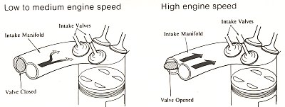
traditional toyota tvis
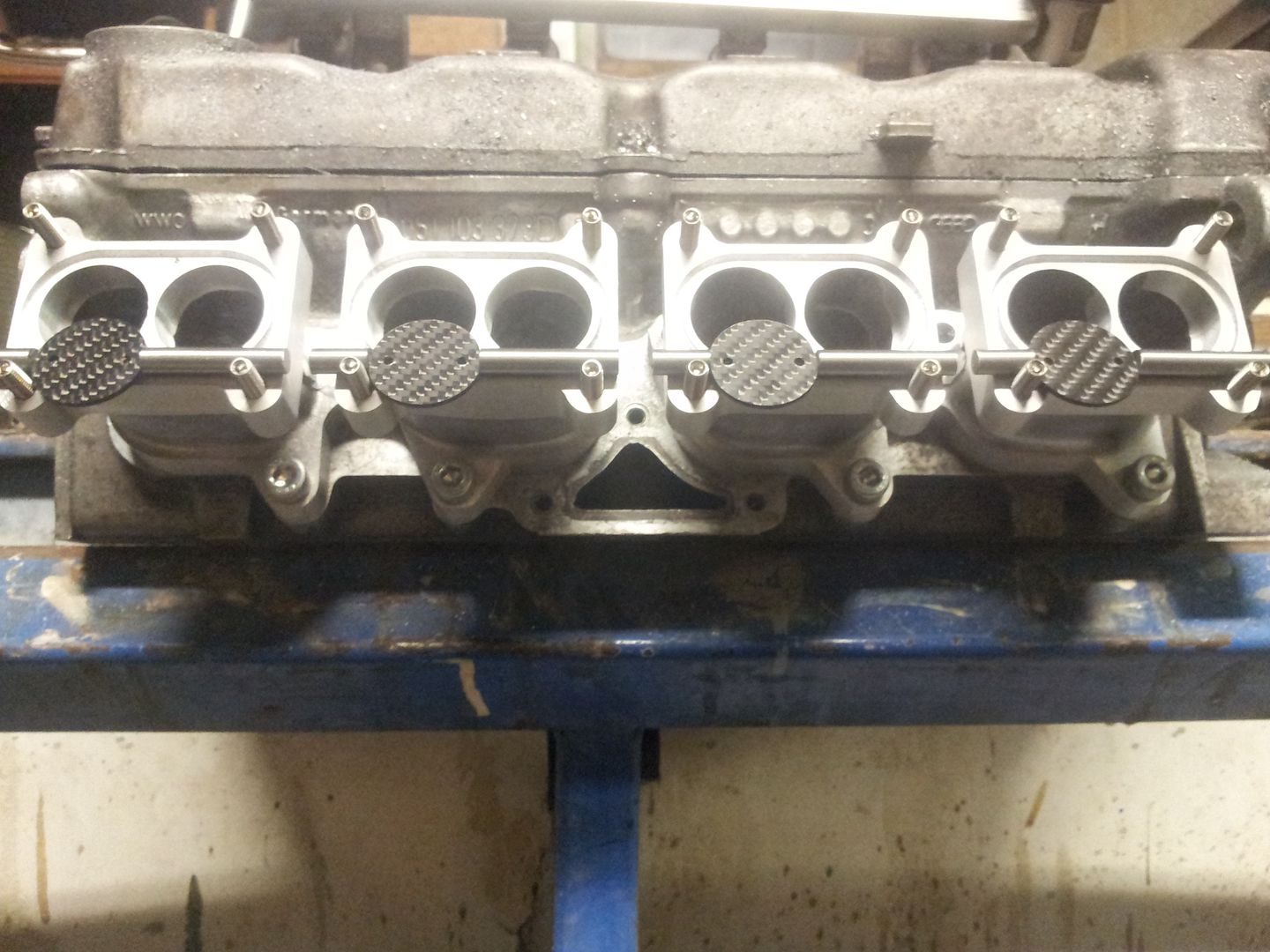
tvis1.jpg


tvisplusmanifold.jpg


M3 ITB

2d8ht3b.jpg


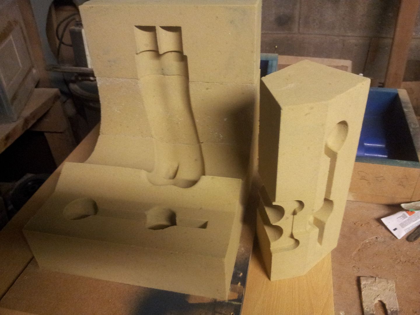
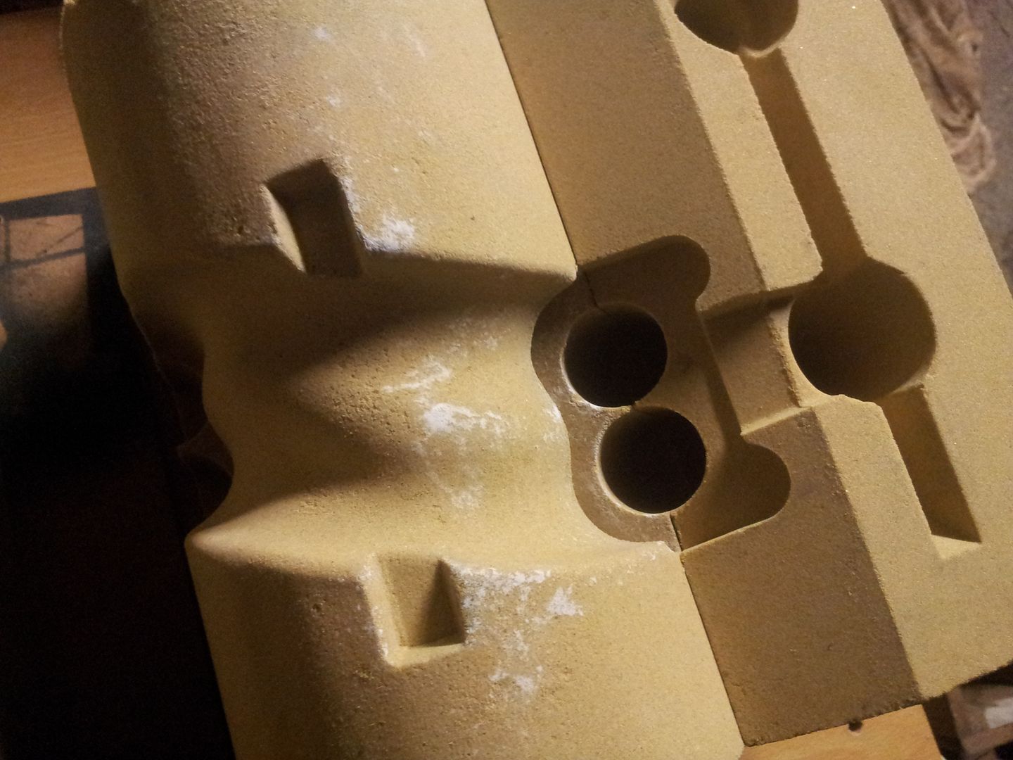
Dual port interal wastegate actuator

17228_06-500x500.JPG
 
Replies continue below

Recommended for you

Not really sure what your're trying to get at with this. Generally, on the torque curve, manifold charge density in the manifold will trump velocity/ram tuning effects. So you would not want to sacrifice manifold pressure for the sake of increased ram tuning, if maximum torque is the goal.

"Schiefgehen will, was schiefgehen kann" - das Murphygesetz
 
Take a look at any 2004-ish through 2010-ish Suzuki or Kawasaki sportbike throttle body. They have two throttles for each cylinder ... one operated by the rider, the second operated by the computer, and at lower revs, the second one is only partially opened if the rider asks for full throttle.

The newer ones have gone full drive by wire with only one set of throttles, but same idea, at certain engine speeds when the rider asks for 100% throttle the computer doesn't open them all the way.

So, not only has it been "experimented with" but it has been in production for years. I suspect that you didn't look outside the automotive world and consider the motorcycle world.
 
Im not really sure either.

I did however make a cast split runner intake manifold system to bring some life back into a 16v vw engine - If i could only find the time to travel 500miles to my nearest RR Ill let you know results. Its similar in principal to the TVIS image above.

Brian,
 
Well if your map sensor is pegged at atmospheric at 30% throttle at lower rpm there is no extra charge density to be gained from the other 70% throttle opening. There is a drastic reduction in velocity though for the same non - gain in density. Higher velocity of equal density equals better cylinder filling and a denser charge where it needs to be when the intake valve closes.

Say for example you are accelerating at low rpm and high load, high gear. Is it possible that holding a smaller throttle opening (still at full atmospheric pressure on the vacuum gauge) could yield more torque and better acceleration than WOT because of a higher intake velocity in the port around the throttle there? Has anyone ever done back to back dyno or accelerometer logs through different throttle openings on an itb setup? I am willing to bet WOT does not result in maximum torque at all rpms.

The variable geometry tvis design I used as an example closes half the effective port area off at lower rpm. This is irrespective of manifold pressure or restriction as I am proposing to account for. It is based on rpm alone, and yet it makes MORE torque where that runner geometry is favorable to wave tuning.

tvis.jpg


I am proposing that at least for cross sectional area, not length, you could tune an itb system as a fully variable version of this principle. The tvis system unlike say a cyclone from mitsubishi, does not even have different length runners it is deactivating at lower rpm, they are the same length, all they are doing is closing down half the flow area. Why is an itb held at half throttle in a single runner much different?
 
BrianPetersen said:
Take a look at any 2004-ish through 2010-ish Suzuki or Kawasaki sportbike throttle body. They have two throttles for each cylinder ... one operated by the rider, the second operated by the computer, and at lower revs, the second one is only partially opened if the rider asks for full throttle.

The newer ones have gone full drive by wire with only one set of throttles, but same idea, at certain engine speeds when the rider asks for 100% throttle the computer doesn't open them all the way.

So, not only has it been "experimented with" but it has been in production for years. I suspect that you didn't look outside the automotive world and consider the motorcycle world.

THIS ^, is exactly what I was looking for and suspected. Thank you. I was aware of sport bikes using dual throttles but did not understand if that was their function. I did try and research it but couldn't find a whole lot of technical information about it's function. Most people seem to just discuss them as chokes and operating at warm up. I think that is maybe a misunderstanding carried over from carby times. Which I understand was not that long ago in the sport bike world.

Well it certainly gives lots of credence to my understanding. Do the factory service manuals detail the function of these secondary throttles? Why have no aftermarket itb manufacturers caught on to this? I don't think the mechanical system i proposed would be that difficult to build and implement for generic applications.
 
BrianGar said:
I did however make a cast split runner intake manifold system to bring some life back into a 16v vw engine - If i could only find the time to travel 500miles to my nearest RR Ill let you know results. Its similar in principal to the TVIS image above.

That is pretty crazy. It's not exactly what I was talking about but still very impressive. Have you got picture or details of your system anywhere online already? I take it RR is rolling road? You could still get very useful information from an acceleromter setup like a gtech, it sounds like the costand time to travel to the dyno alone would offset the cost of a gtech for you.
 
gsxr750_torque.jpg


Not a huge gain but I imagine that pure torque #s are not the entire story. You can hear an engine gasp and play catch up with a large opening of a large throttle even with correct fueling and throttle enrichment, it's worse the heavier the load is and a sport bike is about the best power to weight ratio most any engine will ever see. I am guessing the bigger gains were in transient response time and overall throttle responsiveness.

I think that area of load is probably the least important on a bike vs any other itb application. I'm willing to bet bmws drive by wire has the exact same functionality on the m3.
 
I dont have a picture of it fully complete on this harddrive but here are three ''along the way'' shots that may give you an idea on what the finished 'thing' looked like. It consists of a cast port splitter section with deactivation butterflies - attached to head, and 4 sets of twin runners off that upto a common plenum - the sand mould below is from one of the 4 twin runner sections(minus the cores). Its not what Id call crazy, just some weekend tinkering...

vaributterflies039_zps6bf4b242.jpg


varimouldsand2032_zpsda5e1ec4.jpg


varimouldtrialbuild001_zps5be790ee.jpg


As for travel costs to the RR, Im hoping someone will want me near it someday at their expense and the intake will happen to walk into my suitcase the night before...

Theres another bike intake too where a set of longer trumpets hinge onto short ones at lower rpm to catch a different wave pulse - the name or model wont come to me at the minute.
The long and the short of it in terms of intake manifolds is that 'It all Depends' and 'Everything will be a compromise' 'Excels at a particular rpm over another' and so on....

Brian,

 
The current Yamaha R1 uses the motorized velocity stack arrangement.

Regarding the dual butterfly arrangement, it's true that the RPM range affected by not fully opening the throttles is below the meaty part of the engine's torque curve, but it does affect starting off from a stop (e.g. starting a race - whether roadrace or drag), and for a street ridden bike, that rev range will make it feel more punchy during normal riding at lower revs.

It can be said that the constant-velocity carburetor that was traditionally used (in a one-carb-per-cylinder arrangement) is another form of variable intake runner. In fact, the first generation of fuel-injection on the Yamaha R1 (2002 - 2003) used vacuum-operated slides just like those of CV carbs, they just weren't involved with fuel metering the way a CV carb slide is.

The major redesign in 2004 eliminated the vacuum-operated slides and replaced it with a servo-operated secondary throttle, same as Suzuki and Kawasaki had already been doing.
 
In-cylinder air motion control (tumble, swirl) can be achieved through additional throttling, e.g. through controlled asymmetric flow through multiple intake ports.

- Steve
 
BrianGar, that is a very cool setup, I would like to see pics and hear the results of the finished product.

BrianPetersen said:
It can be said that the constant-velocity carburetor that was traditionally used (in a one-carb-per-cylinder arrangement) is another form of variable intake runner. In fact, the first generation of fuel-injection on the Yamaha R1 (2002 - 2003) used vacuum-operated slides just like those of CV carbs, they just weren't involved with fuel metering the way a CV carb slide is.

I agree, this was a section of the formation of this idea that I had, that I concede is obviously not original, though I did not know for sure if it was in practice anywhere else though I suspected so. In have had experience before installing big holley 4 barrel carbs on big blocks and such and I always preferred the vacuum operated secodaries to manuals. They open based on vacuum in the primary venturi and open as the velocity through the primaries rises, indicating restriction. I imagine the philosophy is fairly similar with the secondary slide valve you are describing on the 02-03. Not that it operates a secondary fuel system but that it is designed to keep velocity high, this is mainly to keep a decent signal in the venturi for the Bernoulli priciple to operate which the carbs fuel metering depends on, but the same general affect is equally as relevant for cylinder filling and port velocity, it was I think merely a secondary affect of keeping the carb functional.

SomptingGuy said:
In-cylinder air motion control (tumble, swirl) can be achieved through additional throttling, e.g. through controlled asymmetric flow through multiple intake ports.

Do you have any more specific information or studies/data about this? Obviously I believe it is true and the emissions aspect was probably another driving force all in it's own right leading oems to develop such a system for factory itbs. It's kind of useless without specifics though, I guess if i play with it and see how it affects tuning I will learn myself as always but it's frustrating knowing other people have done the work and have the data somewhere.

I wondered too what the affects might be of mounting the throttle sideways, so that the higher velocity air was routed around the butterfly and biased to the outside of the intake valves on a 4 valve head.
 
timiacobucci said:
Well if your map sensor is pegged at atmospheric at 30% throttle at lower rpm there is no extra charge density to be gained from the other 70% throttle opening. There is a drastic reduction in velocity though for the same non - gain in density. Higher velocity of equal density equals better cylinder filling and a denser charge where it needs to be when the intake valve closes.
Velocity where?

"Schiefgehen will, was schiefgehen kann" - das Murphygesetz
 
With the motorcycle dual-throttle setups, and single-throttle drive-by-wire setups that don't open the throttles all the way at lower revs, and for that matter with the CV carb vacuum slides, I don't think inertia and velocity has anything to do with it.

A restriction in the intake runner is not only a restriction for airflow coming in but also against airflow going back out. So you intentionally restrict it just a wee bit as the piston comes down the intake stroke ... then during the dwell period near BDC the pressure pretty much equalizes regardless of the restiction... then you restrict that flow from being pushed back out again. The high performance bike engines all have cam timing that is pretty wild by automotive standards and none of them have variable valve timing.

If the intake runners from a 4-valve head are fully separated, you could fully capture the inertia-ramming effects at lower revs by shutting off one of the intake runners. It should also lead to a swirl pattern in-cylinder rather than the usual tumble. It would probably also require dual injectors (or direct-injection) to avoid in-cylinder fuel distribution problems.
 
hemi said:
Velocity where?

timiacobucci said:
So my question is, is it possible there could be a benefit to intentionally limiting the actual itb opening at demanded full throttle to maintain a slight pressure drop across the throttle and maximize port velocity?

BrianPetersen said:
I don't think inertia and velocity has anything to do with it.

I don't understand how it could be anything else. Even carb function is still essentially depending on velocity.

BrianPetersen said:
A restriction in the intake runner is not only a restriction for airflow coming in but also against airflow going back out. So you intentionally restrict it just a wee bit as the piston comes down the intake stroke ... then during the dwell period near BDC the pressure pretty much equalizes regardless of the restiction... then you restrict that flow from being pushed back out again. The high performance bike engines all have cam timing that is pretty wild by automotive standards and none of them have variable valve timing.

I think we are really talking about 2 aspects of the same thing here. The last part of what you are describing, continuing to fill the cylinder as the piston returns back up after bdc while the intake is still open, the only way a smaller opening can act to stop air from pumping back out of the cylinder as it comes up is inertia. It's not that the small opening is limiting air coming back out, it's that it's developed enough inertia with a high velocity going the other way that it continues on and compresses the air trying to push back up in the cylinder. Traditionally this only works at a certain rpm, usually higher for cams with more overlap but the entire idea of variable geometry manifolds is to tune them to achieve that same end at a slower speed with the same camshaft design.

Here is a picture of a datalog from an engine I tuned. Granted it has a big turbo and that confuses the issue here but it's a 2.3L engine with a 90mm throttle.

vzddvp.jpg


Look where I have the marker set, 27% throttle is already almost full atmospheric pressure. 99.8 kpa, 100 is atmo. So what is all the rest of that throttle opening really doing until the turbo spools and fills in the gap there? At that particular rpm without any boost a throttle 70% smaller would make the same torque. It's even worse with big itbs on sport bikes. Those engines really can't justify those throttles until 10k rpm +. At lower rpm it's just killing port velocity and in turn charge inertia which greatly hinders cylinder filling with those big cams. The idea is a variable restriction yes, but not in the sense that it's choking the engine or limiting anything, it's just covering for gross excess.
 
How is changing the throttle area affecting port velocity, if as you say, and and I grant you, at low rpms it is not affecting charged density in the manifold?

"Schiefgehen will, was schiefgehen kann" - das Murphygesetz
 
Regulating airflow using variable duration/lift of the intake valves is a far more efficient approach than using a throttle valve on the intake manifold. The cam phasing devices used on current DOHC engines are able to provide a variable valve timing effect that can function as an intake throttle over much of the engine's operating range.
 
Hemi, I realize it is not altering the actual phsyical port area or valve area, it is definitely accelerating the flow just prior to it though. For example the 4g63 engine I am planning this ITB setup for with a bike throttle like I have planned actually puts the throttle inches away from the intake valve. This distance would acutally still be inside the port of most older over head valve v8s that I have worked on. It's all relative stuff but you would grant that reducing the entrance to a small block chevy intake port at the manifold by 70% will likely result in increased port velocity right?

tbuelna said:
Regulating airflow using variable duration/lift of the intake valves is a far more efficient approach than using a throttle valve on the intake manifold. The cam phasing devices used on current DOHC engines are able to provide a variable valve timing effect that can function as an intake throttle over much of the engine's operating range.

I realize this is true, and direct injection is pretty tick too. It actually seems silly to me to talk about efficiency and throttling in the same breathe. Technologically speaking it makes far more sense to develop direct injection to the point you can fuel throttle the engine and reduce the need for throttling and the resultant pumping loses all together like a diesel.
Both of these technologies are very effective and very unreasonable to try and add to engines that weren't already designed with them from the factory. As far as performance goes though you can't beat the responsiveness of ITBs and the power gains of forced induction and both these things can be applied to just about any internal combustion engine. The specific intention of this discussion was itbs as a variable geometry manifold. If I can build a mechanical linkage using an internal wastegate actuator on sport bike itbs and tune it well that puts it's in a whole different league than trying to add variable valve timing to an engine that never had it.
 
Status
Not open for further replies.
Back
Top