Continue to Site

Eng-Tips is the largest engineering community on the Internet

Intelligent Work Forums for Engineering Professionals

  • Congratulations The Obturator on being selected by the Eng-Tips community for having the most helpful posts in the forums last week. Way to Go!

Variable serrations on a flat surface

Status
Not open for further replies.

NutAce

Mechanical
Apr 22, 2010
1,192
Hi Guys....

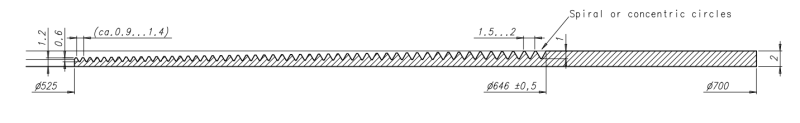
I need a brilliant idea for below problem.

I have a circular gasket with concentric serrations on a conical part of the surface. The concentric Serrations are varying in pitch and height.
I do not want to model it (makes the model unnecessarily heavy) but I would like to show a detailed view on the drawing. So preferably I would like to use a parametric sketch.

Serations_pgov5v.png


Ronald van den Broek
Senior Application Engineer
Winterthur Gas & Diesel Ltd
NX9 / TC10.1.2

Building new PLM environment from Scratch using NX11 / TC11
 
Replies continue below

Recommended for you

How about 3D modeling the serrations, Then process the 3D model to 2D drafting. Then use Snapshot in Lock view options in the in the 2D view.

Then suppress the steps in the model.
 
The way it would have been done in the days of drawing-boards , pens and paper ,
draw the serrations in the section view, only.
"Simplified drawings" works today too.


1) create the gasket without serrations. Create the drawing file etc
2) place view on dwg.
3) create section view, without crosshatch. ( Remember in older NX versions to set Extracted Edges = ON to be able to snap the sketch to the model.)
4) create sketch in section view, draw the serrations
5) use view dependent edit to hide the line of the revolved body where the serrations are.
6) insert crosshatch, use Point in region.

Done. (?)

Regards,
Tomas

 
What I am looking for is a way to create the sketch in a parametric way. Preferably with some Kind of pattern to create the serrations.


Ronald van den Broek
Senior Application Engineer
Winterthur Gas & Diesel Ltd
NX9 / TC10.1.2

Building new PLM environment from Scratch using NX11 / TC11
 
sorry, I didn't understand that that was the question.

Can you draw the first tooth, and then use the Pattern Geometry and somehow... scale each instance ?
I do not , at this point, know how to do that...

Regards,
Tomas
 
Status
Not open for further replies.

Part and Inventory Search

Sponsor