Continue to Site

Eng-Tips is the largest engineering community on the Internet

Intelligent Work Forums for Engineering Professionals

  • Congratulations IDS on being selected by the Eng-Tips community for having the most helpful posts in the forums last week. Way to Go!

Velocity and pressure drop for MEG line 1

Status
Not open for further replies.
Jul 21, 2010
36
Hi all
I am looking for some criteria for velocity and pressure drop/100m for MEG in order to perform line sizing for MEG line and pipeline.
I know general criteria for liquids such as what mentioned in TOTAL or others standards, but winteresting thing for me is special criteria for MEG .
Please let me know if there is such criteria.
Thanks
 
Replies continue below

Recommended for you

Am not aware of any other requirements for MEG-water solutions. Obviously, the pressure drop calc would be done at the lowest operating temp when viscosity would be high.
 
Agree with George, nothing very special about MEG compared to any other clean liquid.

As a general guide, long distance pipelines usually end up with around 2 to 3 m/sec as the most economic velocity, shorter systems sometimes a bit faster.

Each system needs design on its own for your particular requirements, end pressures etc.

E.g. if you're injecting MEG at the end into a high pressure system, the pipe size might need to be bigger to reduce the friction element of the overall pressure.

Do the options, find the best / most economic design for your system.


Remember - More details = better answers
Also: If you get a response it's polite to respond to it.
 
Dear Georgeverghese, dear LittleInch
Thanks for your response, actually i have done my sizing , just wanted to make sure that there is not special consideration for MEG.
Another question which i need to work on it is about turndown ratio for a MEG pipeline.is there any manual or standard which elaborate correct method to especify cright turn down ratio?
Thanks in advance

P.s. There is a pump upstream of pipeline.
 
No - no manual or standard, but anything more than about 4 or 5 to 1 turn down gets very complicated from an equipment / control point of view.

Often you're better off batching it if you can, but if not you might need some different pumps below about 1:3 turndown.

BTW there is no such thing as the right pipe size or right turn down, it's simply the best compromise for your particular situation and drivers

Remember - More details = better answers
Also: If you get a response it's polite to respond to it.
 
Obviously at low flows, the destination pressure will approach pump discharge pressure, since frictional dp will be much less. So the injection fitting has to deal with pressure ranging up to supply pump discharge pressure.
 
I'd say yes. Just make sure you are always in turbulent flow regime and keep MEG at reasonably high temperatures to avoid flow problems at increased viscosity. There is a threshold value above which the pump will not be able to deliver the required flow, unless the entire system is designed for cold start.

meg_dd2lhw.jpg


Dejan IVANOVIC
Process Engineer, MSChE
 
Dear Ivanovic
Thanks a lot for your great post.
Actually in our study we selected 6 inch pipe rather than 4 inch in order to use existing pump and to prevent new pump installation and because there is a good static head available in piping system(around 3 bar static head against 8 bar friction loss).(i have descibed full story in the following topic:
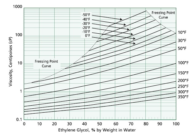
Temperature at piping inlet is ariund 60c and hysys predicts temperature decrease to 31c along pipeline in worst case.Meg is 70%wt and viscosity is around 5.8 cp @31c.also reynold would be 17000 at this condition.however it seams than we should be careful in defining turn down ratio for pipe line.
Therfore according to your chart there would not be any problem.what is your idea?
Would you please let me know reference of your diagram?
Thanks in advance
 
Viscosity chart is taken from MEGlobal

I don't know what economics and design criteria you used to prove that 3km 6" pipeline is cheaper and better option than 4" pipeline and a shipper pump.
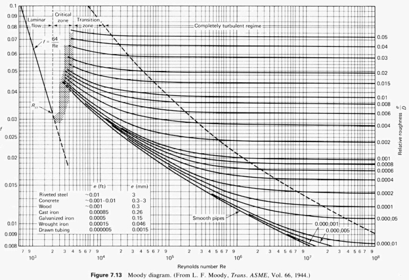
With Reynolds 17,000 you are actually in the transition zone, not in fully developed turbulent flow regime - and you are there for the design (max flow case). Something's wrong there.

Moody_ten7eo.jpg


Dejan IVANOVIC
Process Engineer, MSChE
 
Dear Dejan,
Thanks a lot for your great posts,To be honest i have not compares two options(3 km ,6inch pipe against 3km ,4 inch pipe plus pump and accosiated control valve), but the main reason is that we prefer to do not touch existing package and just take a branch from tie-in point.
Actually i am still worriey a little bit about reynolds number.For 6inch pipe depending on temperature ,reynolds would be between 17000 upto 38000.for 4inch pipe in best condition reynolds would be 58000.for both cases we are not in fully developed regime.velocity for 4inch is 1.33m/s and for 6inch is 0.60m/s.
Maximum flowrate is 40m3/hr and it is normal flowrate because we are going to use package as much as possible in predeterminded time.however in case of selection of 6 inch pipe we should select high turn down ratio(e.g. 80%).
Your and other peopele advice is highly appreciated
 
If the company you work for is an engineering design company, it has to be able to demonstrate why a particular design option has been selected and developed. This, on many occasions, involves cost-benefit analysis, as well as sensitivity analysis and analysis of exposures to various construction and operational risks. That should be your strongest argument in convincing the client why it is better to chose option A versus option B, even if they strongly prefer option B (just an example). Failing to do so will always make your standpoint (whatever it is) weak, and the client can always insist on a more complicated, expensive, less efficient, or even completely wrong solution, because the engineering design team failed to properly evaluate all options, sensitivities, and risks, and present full argumentation for the final selection to the client.

Ask yourself how robust, flexible, and reliable your current design is. Does it allow Operations to move a bit left, right, up and down, is it sensitive on flowrate, soil temperatures, inlet conditions etc. etc. You don't seem yourself convinced that the design you propose (or the client proposes) is good enough or not, or whether there are better (less costly or more costly options). You need to sit with your team and go through what you have developed so far and see what can you do about it. Because it looks like there is quite a few things that could be done.


Dejan IVANOVIC
Process Engineer, MSChE
 
Dear Dejan,
Thanks a lot for your post,
You are completely right.A report considering all economic,operational and constrauction aspects will be prepared.but first of all , I need to be sure that my design is technically acceptable to be considered as an option.I mean if 6 inch case is acceptable then I can compare it with 4 inch case in cost, operation and other point of view.
Best regards
 
For piping and fitting losses in non turbulent flow, use the Darby 3-K method to work out fitting pressure losses. If you dont have the correlations for this method, you can still use the Crane method, but use the friction factor for fully developed turbulent flow for fitting losses, even though your actual flowing friction factor is much lower.
 
Dear Dejan
We are currenting working on using both 4" and 6" size in our pipeline, I mean some part of piping would be 4inch and another part is 6inch.
With this strategy we omit new pump installation and on the other hand using 6 inch pipe woud be economically feasible rather than pump installation case.
Let me know if you or other friends have any idea.
 
You havent said what the application for this MEG is: - note than an aqueous MEG solution can drop out any dissolved salts if the operating temp for this supply line is low, and that can reduce the effective line id, and increase pipe roughness also, so a healthy margin on dp may be required to account for salt deposition. Else an MEG reclaimer / ion exchange unit may be required in the regen circuit to keep TDS low.
 
Dejan,

I think for pipe fully developed turbulent flow is normally once you go past Re of 4000.

Fully developed flow into an open end of a pipe occurs within 40 D.

That line on the chart is misleading for pipe flow. The flow at 4 and 6 inch is fully turbulent IMHO.

If 6 inch is cheaper then it's ok. Have you considered OPEX as well?

Remember - More details = better answers
Also: If you get a response it's polite to respond to it.
 
Dear georgeverghese
Supply line transfers meg plus salt,return pipe line from reclaimer transfers meg containing small amount of salt.
We have calculated pressure drop for supply pipe line at lowest temperature,it means worst case design.
For return pipeline ,meg temperature at inlet is high enough.

Dear Littleinch
Actually capex for 6inch is more than 4 inch plus pump.so, we are going to use option A (1000m 4" pipe and 1500m, 6" pipe without pump) instead of option B (2500m ,4 inch pipe plus pump).
Absoulutly pump opex would impact on overal cost estimation and we should consider it.

 
Status
Not open for further replies.

Part and Inventory Search

Sponsor