Continue to Site

Eng-Tips is the largest engineering community on the Internet

Intelligent Work Forums for Engineering Professionals

  • Congratulations GregLocock on being selected by the Eng-Tips community for having the most helpful posts in the forums last week. Way to Go!

Vertical force at the fixed end if bending moment is applied to the free end on a cantilever beam

Status
Not open for further replies.

Jonnox

Civil/Environmental
Mar 19, 2012
10
Hi All,

quick question, I have a situation where i have a cantilever beam and i have been told that on the free end there is a bending moment load only of 1000 Nm and the overall length of the beam is 2 m.

What would the vertical load be on the fixed end??

Best Regards
Jonnox
 
 Vertical force at the fixed end if bending moment is applied to the free end on a cantilever beam
Replies continue below

Recommended for you

If the load applied at the free end is a pure moment load, then the vertical shear reaction at the fixed support is zero, and the resisting moment there is equal to the applied moment.
Dave

Thaidavid
 
I should have probably also added that moment loads are rarely applied as "pure" moments, given real-world conditions, and the practicalities of connections details. You should probably also include a nominal amount of calculated vertical shear capacity in the fixed connection, based on your engineering judgement.

Thaidavid
 
Hi Dave,

Thank you for your response. I will go into detail a little bit more so you understand my true problem.

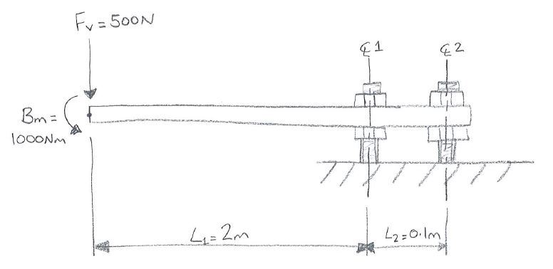
I have a beam that has both a vertical force on the free end and a bending moment (or so I am being told) and I was wondering the best way to assess the problem. Hopefully find attached a picture i quickly drew of the set up i have been presented. I'm wanting to find out what are the loads in the 2 fixing studs/nuts?? I'm not needed to be to accurate as i am also getting some FEA done but I was interested in the best way to tackle this problem by hand calculations.

Load_Case_lzvxce.jpg


Best Regards
Jonnox
 
I'd say the first stud serves as a hinge for the beam and sees only a vertical reaction, the second reacts both moments (Bm and Fv x L1) with a vertical force.
 
The total moment at the fixed end is the approximate sum: 500N(2M) + 1,000N-M = 2,000N-M. Assuming that the plate is much stiffer than the connecting bolts, the tension and compression in the bolts is then respectively: T = C = 2,000N-M/0.1m = 20,000N.
Dave

Thaidavid
 
Thank you for your reply's,

So let me know if I'm getting this correct............

The first bolt will have a load going through in the vertical direction equal to that of Fz. So 500N only?? Does the bending moment not apply anymore force through this bolt?

The second bolt will have a load from the Bm and Fz with the first bolt acting as pivot point?? So as said 500N(2M) + 1,000N-M = 2,000N-M/0.1m = 20,000N.

I'm also looking at what roughly the force will be going into the ground through the bolts.

If the combined bending moment at the first of bolts is 2,000N-M this must put some additional loading on than first bolt other than just the 500N??

Sorry if I'm not getting it completely!

Best Regards
Jonnox
 
Just stretch your plate 2m to the left taking the shear load along for the ride. Then ignore the moment and analyze line any other cantilevered beam. That's statically equivalent and probably a better reflection of how the moment came to pass anyhow.

I like to debate structural engineering theory -- a lot. If I challenge you on something, know that I'm doing so because I respect your opinion enough to either change it or adopt it.
 
This is a fairly simple statics problem that is being made much more difficult than it needs to be. Both bolts would probably best be modeled as pinned supports than can't resist moment individually (assuming nothing is strange about the size of the connection components or the plate). I agree with KootK's response, but here's how I would tackle it:
- Sum the moments around CL1. This allows you to solve for a tension force in the back bolt: 500N*2m + 1000Nm + 0.1m*R2 = 0 ==> R2 = -20,000N
- Sum the vertical forces. This allows you to solve for the compression force in the front bolt: -500N - 20,000N + R1 = 0 ==> R1 = 20,500N

If you put this in any FEA program with the bolts modeled as pinned supports it should verify this (and it wouldn't take more than a few minutes to model it as you have it shown).
 
I'm not sure why this question requires FEA, but if you do it, make sure you understand how the results compare with the theory of basic statics.

If we ignore the moment restraint provided by the bolt heads (which is a reasonable simplification), then we have a straight beam with two simple supports. The solution is as given in previous posts, but can be generalised as:

Take moments about one support to find the reaction in the other support (from moment equilibrium)
Resolve forces to find the reaction in the support you took moments about (from force equilibrium)

Note that the force in the first bolt is very much greater than the applied 500 N load.

Doug Jenkins
Interactive Design Services
 
Status
Not open for further replies.

Part and Inventory Search

Sponsor