Eng-Tips is the largest engineering community on the Internet

Intelligent Work Forums for Engineering Professionals

  • Congratulations waross on being selected by the Tek-Tips community for having the most helpful posts in the forums last week. Way to Go!

Very wide tolerances on non-critical features

Status
Not open for further replies.

JazzSinatra

Mechanical
Jun 11, 2019
4
0
0
FI
What is your opinion about using very loose tolerances on non-critical or functionally inexact features? I use the following simple and fictitious hole as an example:

tolerance-example_wnhgdv.png


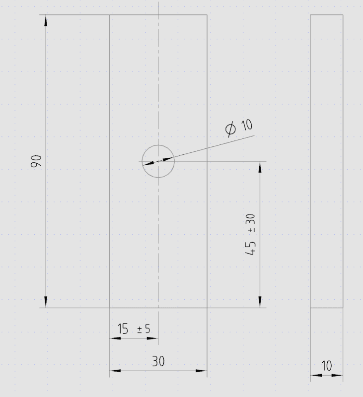
Let's say that the location of the hole in the picture is non-critical, so it can be anywhere on the surface of that beam, but it must not break the edges of the beam. Is it bad or confusing practice to actually dimension a feature to its functional limits (as in the picture) or should it just be defined by general tolerances, when feature is non-critical or inexact? I think that in consumer products it could give bad impression of quality, if pieces don't look always same, but for in-house products, a machinist wouldn't need to reject or ask, if the hole would for some reason be a bit off. Any thoughts about this?
 
Replies continue below

Recommended for you

Having had personal experience with the opposite situation ... I am always of the view that tolerances should be as loose as possible in a way that satisfies requirements (and that can be both functional and aesthetic). Once upon a time, we spent untold hours trying to drill a hole in a casting within an absurdly narrow specified tolerance and could never get it consistent enough ... and then found out that it was for installing a wiring harness clip that could have been placed anywhere on the casting feature (probably give or take 3mm).

If it is for a consumer product and there is some visual importance of consistency, sure, that plays into it, but in your example if the hole position was give or take 2mm in either direction, no one without measuring instruments would notice, and that's enough to make the machinists life easier.

If it's for (as in my example) a wiring harness clip buried on the inside/backside of an automotive instrument panel cross beam that no one but a mechanic doing a major repair is ever going to see and certainly never in a position to compare two parts side by side ... have at it.

Bear in mind that even if the end use of the hole doesn't warrant accurate positional accuracy, automated assembly operations may require some degree of consistency between parts. If the screw is being installed by an automated pick-and-place device, it's going to stab it into the same location every time, and the hole had better be there.
 
It looks incredibly indecisive to me. Choose a tolerance that reflects the tooling and measuring instruments. Or, just leave the tolerances off of the drawing - maybe have a standard tolerance block based on precision of the basic dimension that appears on the drawing border. If it helps, you might cite something like AISC Code of Standard Practice.
 
In this case, I would leave the tolerances off and perhaps include some note about minimum distance from the edges.

John R. Baker, P.E. (ret)
EX-Product 'Evangelist'
Irvine, CA
Siemens PLM:
UG/NX Museum:

The secret of life is not finding someone to live with
It's finding someone you can't live without
 
JazzSinatra,

I have never specified anything that sloppily. I do specify the loosest tolerances that I can. This really is a manufacturing question. How do they react to this?

This might be a good question to ask in forum301.

--
JHG
 
Hopefully, you have some idea of how that hole gets put there, and tolerances could reflect that as well.
If somebody's measuring each piece with a tape measure, then figure +/- 1/8" would be easily achievable.
If they're using a rifle from the other side of the warehouse, then you may need that +/- 30mm.

My brother used to work for a pacemaker manufacturer. The pacemakers came with a lead, which the doctor trims to length when it's installed, so it doesn't really matter what the exact length is. But being a highly regulated medical product, everything had to be just so-so on paper. So the phrase they used was "measure it with a micrometer, mark it with a piece of chalk, and cut it with a hatchet."
 
While I get that "normal" and "practical" results are that your hole will be roughly where you want, it should not be unexpected that someone, at some time, will drill the hole on, or even past, the edge of the bar and demand that the bar be accepted, since you otherwise have no criteria for rejection. You should have some positional tolerance or some demarcation of the area wherein the hole would be acceptable.

TTFN (ta ta for now)
I can do absolutely anything. I'm an expert! faq731-376 forum1529 Entire Forum list
 
Don't talk to me about how to cut the leads to a pacemaker. Three years ago I had to have my Aortic heart valve replaced and we were warned that in 25% of the cases, a pacemaker would need to in implanted after the surgery. Well, sure enough, I 'won the lotto' and they had to implant a pacemaker. Everything was fine, at least for 24 hours and then just as I was being discharged something happened and the pacemaker stopped working and I nearly passed-out. I literally fell into the arms of my nurse who started to immediately pound my back with her fists as my heart had stopped (I was still hooked to the monitors). It restarted about 12 seconds later and they rushed me back to the OR where they had to replace the leads. It seems the doctor had cut them just a bit short the firs time around as he said he should have allowed for more slack. I'm just glad that they came lose when they did and not while my wife was driving 45 miles me back home from the hospital in L.A. They kept me another day just to make sure. Note that I've had no problems since then. In fact, they've put the pacemaker on 'standby' mode since it appears that the nerves which were damaged during valve replacement procedure have regenerated themselves (we were told that this also happened in about 25% of the cases) and I'm now doing my own 'pacing', but they left it in, just in case (at my last checkup I was told that the pacemaker had only kicked in for less than 2% of the time).

John R. Baker, P.E. (ret)
EX-Product 'Evangelist'
Irvine, CA
Siemens PLM:
UG/NX Museum:

The secret of life is not finding someone to live with
It's finding someone you can't live without
 
We had a fun occasion once, where another group at work was have trouble getting their cryocoolers to sufficiently cool the detector, and we suggested they backfill the cavity with neon, since the atmospheric nitrogen would freeze at 77 K and turn relatively insulative. They tried it, and it worked great; too great, as it turned out, because they were now failing the low temperature limit of 55 K.

The irony is that I later found out that the neon backfill solution actually came from that same group a decade earlier. Never did find out why there was a low temperature limit, since these cryocoolers pretty much bottom out at 45 K, regardless, due to the invariable radiative leakage of heat into the cavity.

TTFN (ta ta for now)
I can do absolutely anything. I'm an expert! faq731-376 forum1529 Entire Forum list
 
I've specified this type of dimension in a different way. Probably made some standards people flip out. But my shop folks and quality folks loved it.

I simply drew in a shaded area. Added a note about the hole should be located in this area.

TygerDawg
Blue Technik LLC
Virtuoso Robotics Engineering
 
Honestly, if I saw 45 +/-30 on a drawing, my first thought would be that it's a typo and I'd wonder if it's supposed to be 0.30. It will just cause confusion due to a simple fact that tolerances this wide are (almost) never done.

If the position is non-critical, then you just leave it emtpy (without a tolerance). That's what general tolerances are for.

If you litteraly want someone to just randomly aim with a drill anywhere for speed / convenience sake (or whatever the reason might be for someone to miss by 20 milimeters), just write it as a note.
 
I tried using generous tolerances and the shop response was that engineering must have made an error and 'Are you sure?'. Decided to stay with the accustomed max shop tolerances rather than spend time responding to questions for no cost reduction expected with wider tolerances.

Ted
 
I concur with using standard tolerances for non-critical but functional features. Usually there is no cost savings for opening up standard tolerances further, and the shop floor usually doesn't want the liability to decide, they want your decision on where to stick the hole.

Non-functional features like logos and part markings OTOH can be done with just a shaded zone or note.
 
Tolerances that loose are almost an insult to the shop people, I would just leave it blank and let the general tolerances note cover it. Or maybe print it in Braille for the supposedly blind machinists... Probably get drill bits thrown at me when I walked thru the shop...
 
keyepitts:
Tolerances that loose are almost an insult to the shop people, I would just leave it blank and let the general tolerances note cover it. Or maybe print it in Braille for the supposedly blind machinists... Probably get drill bits thrown at me when I walked thru the shop...

Why would it be insulting? There are certain features whose position really doesn't have any function whatsoever and it doesn't make sense to waste time trying to achieve any sort of accuracy.
For example, if you're making a structure that's meant to be hot-dip galvanized, you need to drill small holes in tubing for air to escape. You can't have any airtight chambers when hot-dipping because thermodynamics.
And no one in their right mind is gonna waste time measuring the position of those holes using a tape measure. You just point the drill at the approximate place where the hole is most appropriate and shoot.

But I get your point. +/-30mm tolerance zone is surely not the way to do it.
 
the type of part would also be a deciding factor.
plastic, sheet metal and machined part.
the type of equipment and it's precision,
other factors is commercial , medical & aerospace.
the critical nature of the product.
the precision of the machine eg shear, die stamping, brake, cnc turn, or mill & on.

forgive but,
Kindly please never let anyone try to guess and under stand what your asking for.
a concise tolerance were a fabricator or machinist looks at your drawing
knows exactly what the requirement is. the worst drawings are is when it forces a fabricator or
inspector to guess what the requirements are.

even a simple wide open tolerance is great.
make simple clear and concise. no guessing.
 
"And no one in their right mind is gonna waste time measuring the position of those holes using a tape measure. You just point the drill at the approximate place where the hole is most appropriate and shoot."

But you would need to specify that the holes go through into the middle, not just score the tube, and that you don't have 10 holes all in the same place, etc etc etc.

Cheers

Greg Locock


New here? Try reading these, they might help FAQ731-376
 
Yeah, in this case, I'd leave the tolerance off and just put a 15 and 45 since it's not essential. Machinists typically prefer if you give them breathing room and more times than not, they have their own default tolerances that they use.
 
Status
Not open for further replies.
Back
Top